Maxwell2D: Animations of electromagnetic waves
This page contains animations of numerical solutions to Maxwell's
equations in a 2D domain (using the Finite-Difference Time-Domain
method, FDTD). A wave is generally excited at the bottom of the domain and
propagates upwards. The interaction with the various distributions of
complex dielectric constant (the square of the refractive index)
demonstrates many phenomena that occur both in nature and in
scientific instruments. The plots below show the field of dielectric
constant - click on them to see the animation of the component of
electric field perpendicular to the plane of the domain.
Wikipedia links: Maxwell's
equations, Finite-difference
time-domain (FDTD) method
Source code
Documents and presentations
- Radiation parametrization and clouds
Hogan, R. J., and
J. K. P. Shonk. Proc. ECMWF Seminar, 1-4 Sept 2008: PDF (includes a
description of the numerical method employed); PPT
Quick links to animation categories
Propagation |
Reflection and refraction |
Particle scattering |
Clear-air scattering
Antennas |
Waveguides |
Diffraction grating |
Michelson interferometer |
Miscellaneous
Propagation

| Propagation of electromagnetic waves in a vacuum. |
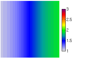
| Propagation of electromagnetic waves in the presence of a
gradient in refractive index. The bending of the wave is what happens
in mirages, shimmering of the light over a hot surface
and anomalous propagation of radar beams.
Wikipedia link: Refraction
|
Reflection and refraction
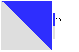 | A
sharp change in refractive index results in specular reflection from
the surface and refraction into the medium according to Snell's law,
with a reduction of the wave speed. The animation shows two panels:
the left shows the complete wave field, while the right shows just the
component that is scattered (calculated simply by subtracting the
equivalent field in a vacuum). The bending of the light explains why
the bottom of a pool of water appears is nearer than it really
is. This kind of reflection is occasionally seen by clear-air
radars as Fresnel scattering from sharp horizontal gradients in
atmospheric refractive index.
Wikipedia link: Snell's law
|
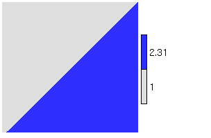 | Consider
light propagating in a medium of higher refractive index incident upon
an interface to a medium with lower refractive index. If the angle
beween the direction of propagation and the normal to the interface is
greater than the critical angle then total internal
reflection will occur. This property is used in the prisms of
bicycle reflectors and is easy to observe when looking through water
into air.
Wikipedia links: Total
internal reflection, Evanescent
wave
|
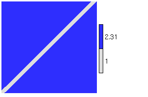 |
Consider the same set-up as with total internal reflection, but
introducing a new medium a distance of order a wavelength away from
the original interface. In this case, there is still some propagation
across the gap, a phenomenon known as frustrated total internal
reflection.
Wikipedia links: Total
internal reflection, Evanescent
wave
|
Particle scattering
 | A small point with a different
refractive index to its surroundings oscillates as a dipole under the
influence of the incident electric field, and reradiates energy in all
directions. In 3D this is known as Rayleigh scattering and
atmospheric examples are scattering of sunlight by molecules
and scattering of weather radar beams by cloud and rain
droplets.
Wikipedia link: Rayleigh scattering
|
 | As the previous
example, but this time the point is illuminated with two frequencies
simultaneously. It is found that the higher frequency is scattered
much more effectively than the lower frequency, explaining why the
sky is blue.
Wikipedia link: Rayleigh scattering
|
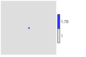 |
When the particle size approaches the wavelength of the radiation
then the front and back of the particle do not experience the same
incident electric field and so there is interference of the scattered
wave from the different parts of the particle. The result is that
forward scattered waves constructively interfere and backscattered
waves destructively interfere, i.e. there is a preference for
forward scattering. The scattered amplitude in the animation is
shown at twice its true amplitude. Atmospheric examples are a
reduced backscatter for high-frequency cloud radars when looking at
larger particles such as raindrops and large snowflakes and the
corona around the sun when it passes through aerosol and haze
particles. |
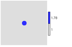 |
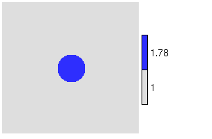
As the particles become larger the width of the forward scattered
lobe becomes narrower. The degree to which this occurs is important
for interpretting multiply-scattered lidar signals as the
forward-scattered radiation stays within the field-of-view of the
receiver. |
 |
Even larger particles exhibit more complex scattering patterns;
scattering by large spheres of constant refractive index can be
calculated exactly using Mie theory. The preferential
scattering in particular directions leads to rainbows.
Wikipedia link: Mie theory
|
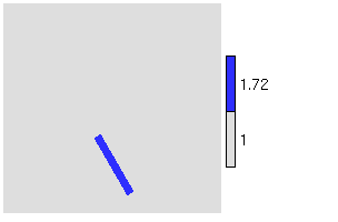 |
Internal reflections and refraction on the flat surfaces of ice
crystals leads to scattering in particular directions and explains
various optical phenomena in ice clouds. |
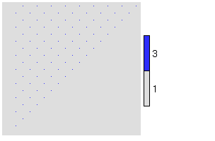 | Bragg scattering is
used to probe the structure of crystaline solids with X-rays. Each
atom in a lattice behaves similarly to a Rayleigh scatterer under the
influence of the incident wave, and certain wavelengths result in
constructive interference in particular directions. This enables the
structure of the material to be inferred.
Wikipedia link: Bragg
scattering |
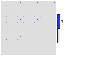 | A further example of Bragg
scattering using the same configuration of atoms as before, but with a
higher frequency resulting in a different scattering pattern.
|
Refractive index inhomogeneities
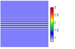 |
When there are fluctuations in refractive index on the scale of
half the wavelength of the radiation, then the scattered waves
constructively interfere in the backward direction (note that the
apparent scattered wave travelling in the forward direction in this
example is simply the energy extracted from the incident wave. This is
how clear-air radars work, for which it is often referred to
misleadingly as Bragg scattering. |
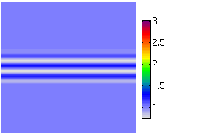 | When the fluctuations
in refractive index are not on the scale of half the wavelength (such
as the example here where they are on the scale of the wavelength
itself) then destructive interference means that no significant
backscatter is detected. |
Antennas
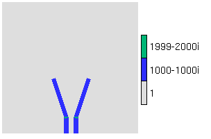 | A horn
antenna is commonly used as the feed for a dish antenna, and
simply consists of a flaring at the end of a waveguide that results in
a reasonably confined beam.
Wikipedia link: Horn antenna
|
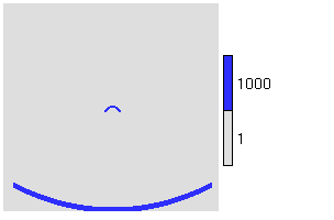 |
This animation illustrates a parabolic dish antenna,
which converts the spherical wave from a simple horn antenna (the
"feed horn") into a plane wave. The very high refractive index of the
curved metal surface acts as a near-perfect reflector. Weather
radars use this kind of antenna.
Wikipedia link: Parabolic antenna
|
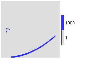 | An Offset dish
antenna is also parabolic, but the feed horn is offset and
only one half of the parabola is illuminated. This prevents the feed
from obstructing the outgoing plane wave. The CloudSat spaceborne
cloud radar uses this kind of antenna for both transmition and
reception (shown by the next example).
Wikipedia link: Offset dish antenna
|
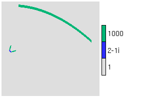 | The same offset dish
antenna as in the previous example can also be used for
receiving. Domestic satellite receivers tend to use this kind
of antenna.
Wikipedia link: Satellite dish
|
 | A phased array
antenna utilizes a number (in this case five) of dipole
antennas that oscillate in phase. The constructive/destructive
interference pattern results in a main lobe of energy in the direction
of interest and a number of weaker side lobes. Clear-air radars
tend to use this kind of antenna.
Wikipedia link: Phased array
|
 | The configuration
is as in the previous example, except that the dipole antennas now
oscillate out of phase. The result is that the beam can be scanned
electronically. This is the way that a wind profiling radar
works.
Wikipedia link: Phased array
|
Waveguides
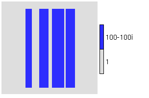 |
A microwave waveguide is normally a hollow metallic
conductor, and must be more than half a wavelength in diameter to
support electromagnetic waves without strong losses. In this animation
the same frequency wave is passed along waveguides with different
diameters.
Wikipedia link: Waveguide
(electromagnetism)
|
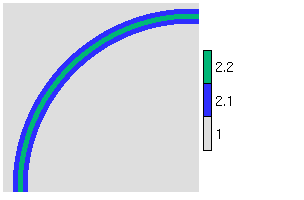 |
An optic fibre has a core with a slightly higher refractive
index than the cladding layer surrounding it, and can act as a
waveguide for light. This animation shows a single-mode optic
fibre, in which the diameter of the core is of the same order as the
wavelength of the light, such that only one mode of wave can be
supported.
Wikipedia link: Optic fiber
|
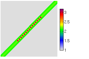 |
A fibre Bragg grating is an optic fibre with
fluctuations of refractive index in the core. This leads to full
transmission of all wavelengths except those close to the Bragg
wavelength. In this example a wave with this wavelength is
propagated along such a fibre.
Wikipedia link: Fiber Bragg grating
|
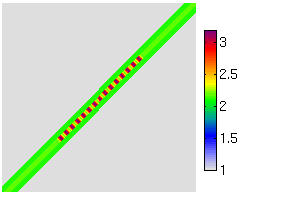 |
The fibre is as in the previous example, but this time the wave
has a slightly shorter wavelength than the Bragg wavelength leading to
complete transmission.
Wikipedia link: Fiber Bragg grating
|
Diffraction grating
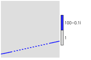 |
A diffraction grating diffracts light by an angle
that depends on its wavelength. It consists of a series of equally
spaced groves of a similar spacing as the wavelength of the
radiation. The simplest way to understand how it works is using
Huygens' Principle; each grove acts like a separate source of
electromagnetic waves, but the phase of each is offset from that of
its neighbours to a degree that depends on the angle of the grating
with respect to the incident ratiation. The diffraction angle is that
which results in a constructive interference between all the different
sources. The sources also combine constructively in the direction of
the incident radiation.
Wikipedia link: Diffraction grating
|
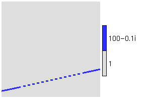 |
This example uses exactly the same grating as above, but the frequency has
been increased by 50%. It can be seen that the diffraction angle is smaller,
and there is a weaker second-order diffraction towards the right.
Wikipedia link: Diffraction grating
|
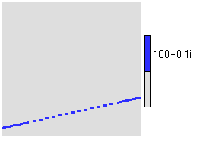 |
This example again uses the same grating as above, but two
frequencies are incident on it simultaneously. This demonstrates the
ability of the grating to separate the different frequencies by
different angles.
Wikipedia link: Diffraction grating
|
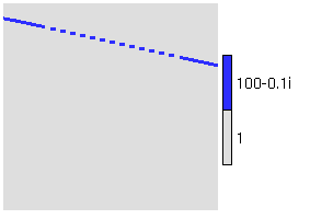 | A reflection
grating is a type of diffraction
grating that exploits the frequency dependence of the angle of
reflection from a device with groves that have a spacing of the same
order as the wavelength of the light. In this case two frequencies are
incident on a reflection grating. Both are reflected significantly in
the direction one would expect if the grating were a
mirror, but the light is also diffracted into beams at an angle that
is frequency dependent.
Wikipedia link: Diffraction grating
|
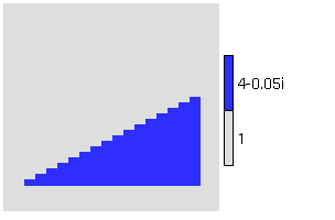 | A grism is a prism
on which has been etched the grooves of a diffraction grating. It is
used in astronomical instruments to filter light into different
frequencies. In this example, two frequencies enter the prism from the
base, and on leaving the other side, a significant fraction of the
radiation is refracted in the direction that would be expected for a
usual prism. However, there is an additional diffracted component, the
angle of which is frequency dependent.
Wikipedia link: Grism
|
Michelson interferometer
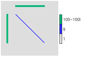 |
A Michelson interferometer was used in the famous
Michelson-Morley experiment to demonstrate the non-existence of the
luminiferous aether, a hypothetical medium in which light was
believed to travel. In the configuration to the left, coherent light
is incident on a 45° half-silvered mirror (in this case simply a
thin bar with a refractive index chosen such that half the light is
transmitted and half is reflected). The transmitted and reflected
beams travel equal paths to ordinary mirrors (in this case simply bars
with a very high refractive index), and are reflected back and
recombine at the 45° mirror. This results in constructive
interference for the outgoing beam to the right. If the luminiferous
aether existed and the earth was moving with respect to it, then light
would be expected to travel at different speeds along the two
orthogonal paths, resulting in a change in the interference behaviour
depending on the orientation of the instrument and the time of
year. The fact that this behaviour was not observed demonstrated that
this aether did not exist.
Wikipedia links: Michelson
interferometer, Michelson-Morley experiment
|
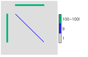 | A Fourier transform
spectrometer consists simply of a Michelson interferometer
but with with one of the two mirrors movable. When one of the path
lengths is changed by a quarter of a wavelength (as in this example),
the radiation from the two paths destructively interferes in the
rightward direction. Instead, the light constructively interferes in
the downward direction (unlike in the previous case). The frequency
spectrum of incoming light may be obtained by measuring the intensity
of the outgoing radiation to the right as a function of the path length,
then performing a Fourier Transform on it. This principle is used by a
number of meteorological satellites instruments, such as AIRS
and IASI.
Wikipedia link: Fourier
transform spectroscopy
|
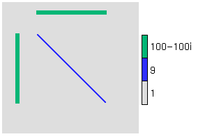 | The same mirror
configuration as in the previous example, but now two frequencies are
used simultaneously. It can be seen that only one of the two
frequencies emerges to the right. Again, the frequency dependence of
the transmission is key to the workings of a Fourier Transform
spectrometer.
|
Miscellaneous
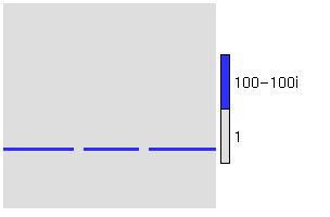 |
This animation illustrates Young's double-slit experiment
demonstrating the wave nature of light. An oscillating dipole
illuminates two slits in a metal barrier, which themselves act as
coherent oscillators that produce an interference pattern at the top
of the domain.
Wikipedia link: Double-slit
experiment |
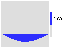 |
The focussing effect of a convex lens.
Wikipedia link: Convex lens
|
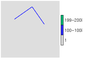 | A corner
reflector reflects radiation back in the direction from which it
came over a wide range of acceptance angles. They can be used to
calibrate meteorological radars.
Wikipedia link: Corner reflector
|
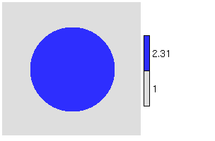 | Campbell-Stokes sunshine
recorders are widely used to record the duration of bright
sunshine during the day. A glass globe focusses the light on to a card
and as the sun moves across the sky, a scorch mark is left on the
card, the total length of which is proportional to the number of hours
of bright sunshine.
Wikipedia link: Campbell-Stokes
recorder
|
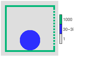 | Microwave
ovens utilize microwave radiation with a wavelength of around
12 cm (2.45 GHz). The holes in the window are much smaller than the
wavelength and hence virtually no radiation can escape. At this
frequency, the water in food absorbes microwave radiation via the
imaginary part of the refractive index.
Wikipedia link: Microwave oven
|
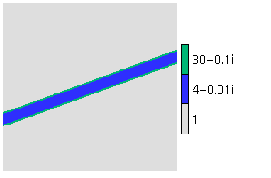 | A Fabry-Perot
etalon consists of a dielectric material between two
reflective surfaces, and only permits light to pass through it if the
wavelength is such that there is constructive interference of the
internal reflections.
Wikipedia link: Etalon
|
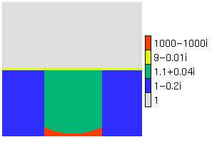 | A laser consists of a
gain medium in which light is amplified: this may be represented by a
dielectric constant with a positive imaginary part. The medium lies in
a resonant cavity, consisting of two mirrors allowing light to reflect
back and forth. One of the mirrors is half silvered, which is where
the coherent laser beam is emitted.
Wikipedia link: Laser
|
Limitations
- A sponge layer absorbs waves leaving the domain, but this is not
perfect so there are sometimes odd effects at the edge of the domain.
- The simulations are two-dimensional, so effectively we have
assumed the dielectric constant to be constant in the third
dimension. This means that in the "Particle scattering" section we are
not strictly simulating Rayleigh and Mie scattering, but actually the
scattering for wires of different diameters. Nonetheless, most of the
same phenomena are observed.
Future ideas
- Hexagonal crystals
- Explanation for the extinction paradox
- Slotted waveguide

|