AIM: To simulate cyclogenesis and examine structures embedded within mid-latitude cyclones which are difficult to observe directly in the atmosphere.
MOTIVATION: The energetics of mid-latitude weather systems are commonly explained by considering the linear stability of simple analogues. For instance, the basic state of the Eady model is baroclinically unstable due to latitudinal temperature gradients at the top and bottom boundaries, and the associated vertical wind shear. Here we present baroclinic wave life cycles which provide an intermediate step between linear stability analysis and observed cases of cyclogenesis. As the waves mature nonlinearly, fine-scale structures develop which closely resemble those observed in the atmosphere. Such knowledge can be used to indicate regions within weather systems which require detailed observation. Also structures can be characterised so that simpler models can be used to explore the wide range of secondary behaviour within cyclones which can impact upon weather locally, and upon mixing of chemical pollutants.
AN EXAMPLE: The basic state for this baroclinic life cycle is zonally symmetric and mimics a latitudinal cross-section through a mid-latitude stormtrack, such as found over the North Atlantic. There is a strong vertical wind shear in the troposphere with a jet maximum at 42N. The fastest growing normal mode with zonal wavenumber six, obtained by linear stability analysis of the jet, is added to the basic state and allowed to develop nonlinearly using a dry, frictionless primitive equation model. The baroclinic wave grows exponentially and by day 4 begins to saturate at the ground where the initial amplitude was largest, forming fronts. In this life cycle the warm front is much stronger than the cold front and a region of warm air is cut off within the cyclone. The upper level wave is characterised by a tongue of Ertel potential vorticity (PV). Since the flow is adiabatic the PV tongue marks the descent of cold, stratospheric air which moves equatorwards and turns cyclonically.
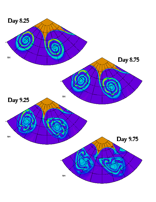
By day 8 the tongue has wrapped cyclonically into a spiral with
three turns (see Figure 1). Undulations on the
filament grow rapidly over the next day, accelerating the mixing
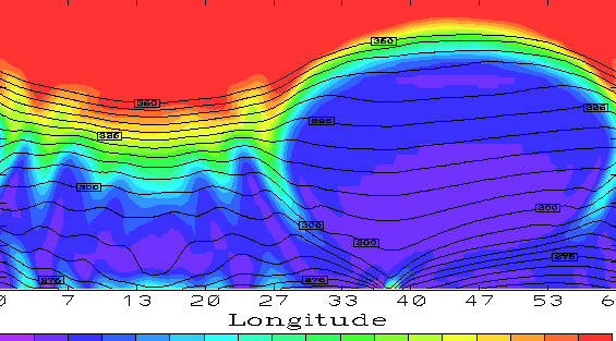
within the vortex. A vertical section through the mature system is
given in Figure 2
DISCUSSION: The structure of fronts and tropopause troughs within a weather system has been seen in fine detail. In particular, the spiral structures are seen to behave like 2-D spirals in vorticity. Using this simplified dynamics and a characterisation of spiral ``tightness'', the stability of the wide range of spiral shapes which may occur in the atmosphere can be explored. Fast growing disturbances such as these, which are typically not resolved in forecast models, will rapidly increase the interfacial area between air masses with different origins and thus promote mixing.
RELATED PAPERS:
Methven, J. and Hoskins, B., 1998: Spirals in potential
vorticity. Part I: Measures of structure. J.Atmos.Sci.,
55, 2053-2066.
Methven, J., 1998: Spirals in potential vorticity. Part II:
Stability. J.Atmos.Sci., 55, 2067-2079.
Advection by atmospheric flows results in the rapid generation
of fine-scale tracer structures. This is true even though the wind
field is typically dominated by large scale features, such as synoptic
scale weather systems. Coarse-grained representations of atmospheric
winds can generate fine-scale tracer filaments, through the chaotic
advection process, which may qualitatively and even quantitatively
resemble those simulated by high resolution winds because the small
scale features in the wind field have less influence on tracer
distributions. This property forms the basis for the contour
advection technique (hereafter CA) in which particles
representing contour positions are advected using winds interpolated
to particle positions from analyses which are spatially and temporally
discretised. For example, Figure 3
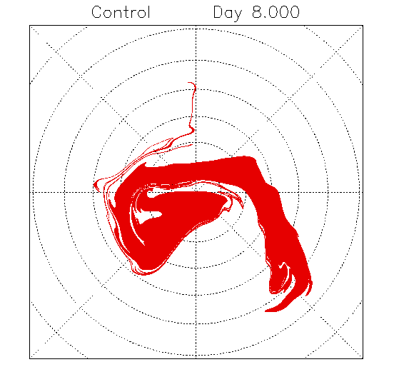
It is shown that although contour stretching rates are very insensitive to the spatial truncation of the wind field the displacement errors in filament position are sensitive. A quantitative lower estimate is obtained for the tracer scale factor (TSF): the ratio of the smallest resolved scale in the wind field to the widest unbelievable filament width (above which all filaments are accurately positioned by a CA simulation). For a baroclinic wave life cycle the TSF=6.1+-0.3 whilst for the NH wintertime lower stratosphere the TSF=5.5+-0.5. Filaments which roll-up due to lateral shear instability were found to be hard to simulate accurately because the undulation amplitude was grossly under-represented, reducing the TSF locally towards unity. CA simulations have a tendency to produce artificially smooth contours, especially when the temporal resolution of the wind is poor.
RELATED PAPER:
Methven, J. and Hoskins, B., 1999: The advection of high resolution tracers by low resolution winds.
J.Atmos.Sci.,
56, 3262-3285.