PHYS 4.3: Electromagnetic forces |
PPLATO @ | |||||
PPLATO / FLAP (Flexible Learning Approach To Physics) |
||||||
|
1 Opening items
1.1 Module introduction
Many of the devices with which we are familiar in everyday life rely for their operation on the forces exerted by magnetic fields on electric currents. Sometimes the electric current flows through wires, such as in the electric motor, and sometimes the force is exerted directly on moving charges, with no conductor present, as in the case of the electron beam in a television picture tube. Section 2 deals with the forces on currents, including those in electric motors and electric meters, whilst Section 3 considers the forces exerted directly on moving charges. The force on a current can produce a torque, and this is utilized in meters and motors. Magnetic fields due to currents also give rise to forces between current carrying wires, and lead to the basic definition of the ampere. In Section 3 our attention turns to individual charged particles in magnetic fields. The basic equation for the magnetic force on a single charged particle is used to define a magnetic field, and then to show that a charged particle in a magnetic field can undergo circular or helical motion at the cyclotron frequency. Section 4 considers the case of a charged particle moving through a combination of magnetic and electric fields and introduces the electromagnetic force or Lorentz force and the Lorentz force law. In Section 5 we end with several applications of the Lorentz force, including the velocity selector, the mass spectrometer, the electromagnetic flowmeter and the Hall effect.
Study comment Having read the introduction you may feel that you are already familiar with the material covered by this module and that you do not need to study it. If so, try the following Fast track questions. If not, proceed directly to the Subsection 1.3Ready to study? Subsection.
1.2 Fast track questions
Study comment Can you answer the following Fast track questions? If you answer the questions successfully you need only glance through the module before looking at the Subsection 6.1Module summary and the Subsection 6.2Achievements. If you are sure that you can meet each of these achievements, try the Subsection 6.3Exit test. If you have difficulty with only one or two of the questions you should follow the guidance given in the answers and read the relevant parts of the module. However, if you have difficulty with more than two of the Exit questions you are strongly advised to study the whole module.
Question F1
A particle of mass m and charge q moves with velocity υ into a region of uniform magnetic field B at an angle θ tο B. Show that the resultant path is a helix. Obtain expressions for the period of the motion and for the pitch of the helix.
Answer F1
The velocity of the particle can be split into component vectors of magnitudes υ| | = υ cos θ and υ⊥ = υ sin θ in the directions parallel and perpendicular to B. The magnetic field interacts only with the perpendicular component of velocity to produce circular motion with a centrally directed acceleration of magnitude a = Bqυ⊥/m, a radius of r = mυ⊥/qB, and a period of T = 2πm/qB. Whilst the particle moves around its circular path perpendicular to B, it also continues its unmodified linear motion parallel to B. The combination of circular and linear motions is a helix, which has a pitch (or axial distance between successive turns) given by υ| |T = 2πmυ| |/qB.
Question F2
Explain why a commutator is needed to feed the current to the coil of a simple d.c. motor. Describe a split ring commutator and its function.
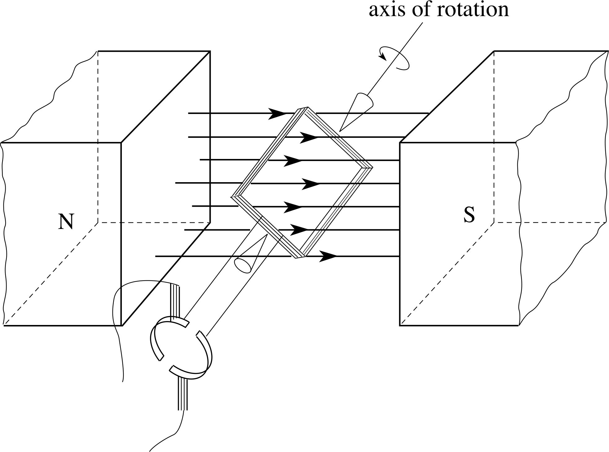
Figure 6 A simple d.c. motor.
Answer F2
A current carrying coil placed in a uniform magnetic field will experience a torque which tries to turn the coil so that its plane is perpendicular to the magnetic field. As the coil turns through this position the direction of the torque will be reversed and the coil will eventually come to rest in the perpendicular orientation. A motor requires the direction of the torque to be maintained as the coil passes through the perpendicular position. This is achieved by a split ring commutator as in Figure 6. Sliding contacts connect the motor’s power supply to the split rings, and the gaps are oriented so that the the current in the coil is reversed as the coil passes through the perpendicular position.
Question F3
A beam of positive ions, all having the same charge q but of various speeds and masses, passes through a region of uniform electric and magnetic fields which are perpendicular to one another and to the initial beam direction. Show that only those ions with a certain speed will pass undeflected through the field region and evaluate that speed.
Answer F3
For a particle to pass undeflected through a region containing both electric and magnetic fields, the Lorentz force acting on it in that region must be zero. If E, B and υ are in the positive x–, y– and z–directions, respectively, then the electric force, magnitude qE, and the magnetic force, magnitude qυB, will have opposite directions along the x–axis. If qE = qυB then the resultant force is zero, so those particles with a speed υ = E/B will be undeflected.
Question F4
Two long straight wires are placed parallel to one another at a separation of r = 12 cm. Wire 1 has a current I1 = 2 A; wire 2 has a current I2 = 8 A. Both currents are in the same direction. Find the force on a 10 cm length of each wire (use μ0 = 4π × 10−7 T m A−1). Will the force be attractive or repulsive?
Answer F4
Wire 2 lies perpendicular to a field of magnitude B2 = μ0I1/2πr due to I1. A length l of wire 2 therefore experiences a magnetic force of magnitude Fmag = B1I2l = μ0I1I2l/2πr. Similarly, wire 1 lies in a field B2 due to I2, and a length l of wire 1 experiences a force of magnitude Fmag = B2I2l = μ0I1I2l/2πr.
So, for either wire, the force on a 10 cm length has magnitude:
$F_{\rm mag} = \rm \dfrac{4\pi\times10^{-7}T\,m\,A^{-1}\times2\,A\times8\,A\times0.10\,m}{2\pi\times0.12\,m} = 2.7\times10^{-6}\,N$
(since 1 T = 1 N A−2 m−2)
As the currents are in the same direction, the force is attractive.
Question F5
A uniform magnetic field of 0.08 T produces a Hall voltage VHall = 2.6 mV when there is a current of 10 mA in a rectangular specimen of a semiconductor. The thickness of the specimen, measured in the direction of the magnetic field, is 0.5 mm. Establish the necessary equations and find the concentration of mobile charged particles in the specimen.
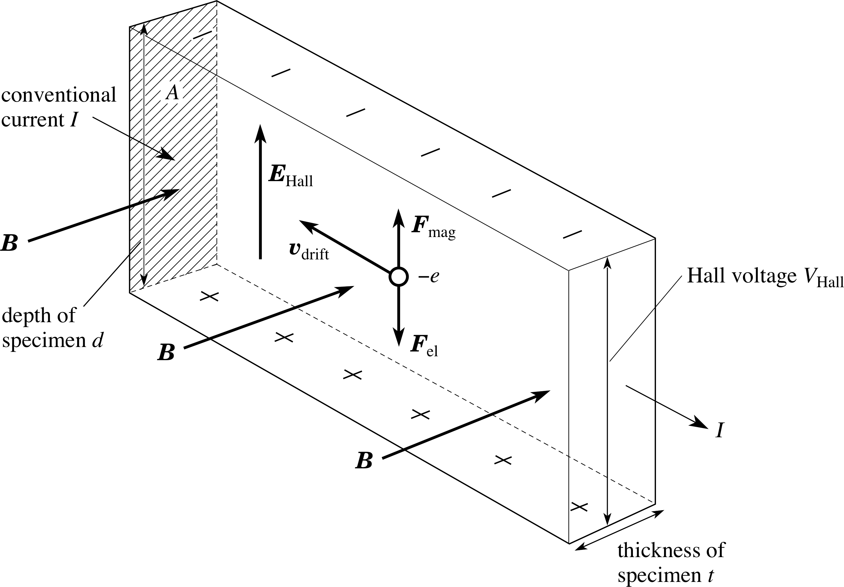
Figure 21 The Hall effect in a rectangular specimen.
Answer F5
See Figure 21. Mobile particles, each of charge e and drifting at speed υdrift constitute the current in the specimen. If the number density of charge carriers is n, and the specimen has thickness t and width d (i.e. an area of cross section d × t ) then the current I is
I = dtneυdrift
In a transverse magnetic field B, a transverse electric field E builds up so that the electric force, magnitude eE, is equal and opposite to the magnetic force, magnitude Beυ, on a moving particle. The electric field has a magnitude E = VHall/d and so
Beυdrift = Ee = VHalle/d
henceυdrift = VHall/Bd
Substituting for υdrift in the first equation gives
I = dtneVHall/Bd = netVHall/B
so,$n = \dfrac{IB}{etV_{\rm Hall}} = \rm \dfrac{10^{-2}\,A\times0.08\,T}{1.6\times10^{-19}\,C\times0.5\times10^{-3}\,m\times2.6\times10^{-3}\,V} = 3.9\times10^{21}\,m^{-3}$
1.3 Ready to study?
Study comment In order to study this module, you will need to be familiar with the following terms: atom, centripetal acceleration, centripetal force, centre of mass, charge, components_of_a_vectorcomponent (of a vector), electric current, electric field, electric force, electron, frequency, ion, line_of_actionline of action of a force, magnetic field, magnitude_of_a_vector_or_vector_quantitymagnitude (of a vector), Newton’s laws of motion, period, potential difference, speed, vector, velocity and you should be able to describe the magnetic field due to a current in a long straight wire. If you are uncertain about any of these terms then you can review them now by reference to the Glossary, which will also indicate where in FLAP they are developed. The following questions will allow you to establish whether you need to review some of the topics before embarking on this module.
Question R1
A ball has a velocity of 20.0 m s−1 at an angle of 55° above the horizontal. Find the horizontal and vertical components_of_a_vectorcomponents of its velocity.
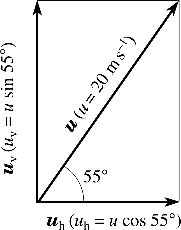
Figure 23 See Answer R1.
Answer R1
See Figure 23. The horizontal and vertical components uh and uv are:
uh = 20.0 m s−1 × cos 155° = 11.5 m s−1
uv = 20.0 m s−1 × sin 55° = 16.4 m s−1
Consult component of a vector and velocity in the Glossary for further information.
Question R2
The passengers on a fairground ride move in a horizontal circle of 8.0 m radius, taking 7.0 s to complete one orbit. What is their centripetal acceleration? What would be the period to complete an orbit for the centripetal acceleration to be 9.8 m s−2 (i.e. one g)?
Answer R2
The orbital speed υ is given by the circumference 2πr of the circular path divided by the period T:
υ = 2πr/T = 2π × 8.0 m/7.0 s = 7.2 m s−1
The magnitude_of_a_vector_or_vector_quantitymagnitude of the acceleration towards the centre is:
a = υ2/r = (7.2 m s−1)2/8.0 m = 6.4 m s−2
The magnitude of the acceleration may also be written as
a = (2πr/T)2/r = 4π2r/T 2
So, if the acceleration magnitude were 9.8 m s−1, the period would be
T = (4π2r/g)1/2 = (4π2 × 8 m/9.8 m s−2)1/2 = 5.7 s
Consult the relevant terms in the Glossary for further information.
Question R3
(a) Describe, as fully as possible, the configuration of the magnetic field produced by a direct current I in a long straight wire. (Consult the answer to this part of the question before attempting part (b).)
(b) Two long straight parallel wires, separated by a distance of one metre, carry currents of 5 and 10 A, in the same direction. Find the position on the perpendicular line joining the wires where the magnetic field is zero.
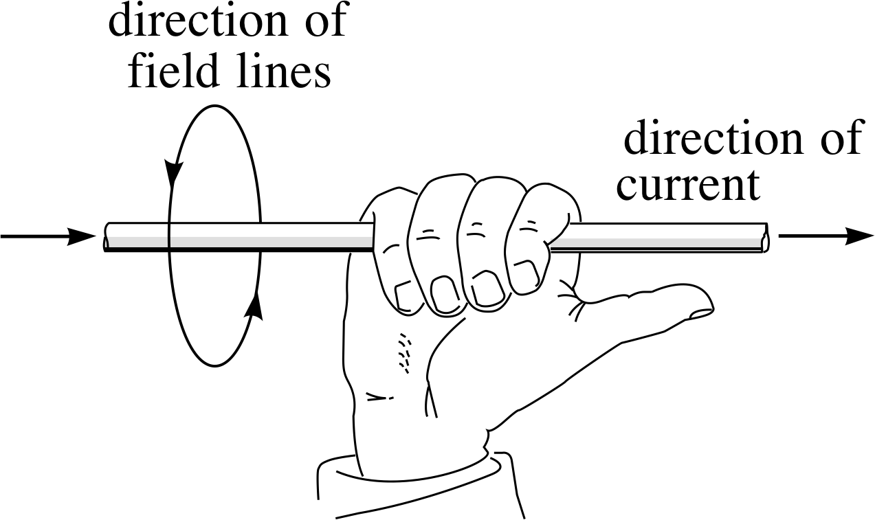
Figure 24 See Answer R3.
Answer R3
(a) The right–hand grip rule indicates the direction of the magnetic field produced by a current: close the palm of your right hand and point your thumb in the direction of the current – the fingers then curl about the pointing thumb in the same sense that the magnetic field curls about the current (see Figure 24).
The magnitude_of_a_vector_or_vector_quantitymagnitude B of the field diminishes as 1/r, according to the expression: B (r) = μ0I/2πr, where r is the perpendicular distance from the wire, and μ0 = 4π × 10−7 T m A−1 is the permeability of free space.
(b) For the two fields to be equal and opposite (and therefore give a resultant of zero) at a point which is a distance r from the current I1, and a distance (d − r) from current I2 (with the separation of the wires taken as d) we require:
$\dfrac{\mu_0I_1}{2\pi r} = \dfrac{\mu_0I_2}{2\pi(d-r)}$
hence (d − r)I1 = rI2 and $r = \dfrac{I_1d}{I_1+I_2} = \rm \dfrac{5\,A\times1\,m}{15\,A} = 0.33\,m$
Consult magnetic field in the Glossary for further information.
Question R4
A potential difference of 100 V is applied between two parallel plates 20 cm apart. What is the electric field between the plates? Calculate the magnitude_of_a_vector_or_vector_quantitymagnitude of the force on an electron between the plates. i How would the force on a doubly–charged helium ion (He2+) between the plates differ from that on an electron?
Answer R4
The magnitude_of_a_vector_or_vector_quantitymagnitude of the electric field is given by
E = V/d = 100 V/0.20 m = 500 V m−1 (i.e. 500 N C−1)
The magnitude of the electric force on a particle with charge e is:
Fel = eE = 500 N C−1 × 1.6 × 10−19 C = 8.0 × 10⁻¹⁷ N
The direction of the force on a helium ion (He2+) would be in the opposite direction to that on the electron, and its magnitude would be twice as large.
Consult electric field and electric force in the Glossary for further information.
2 Magnetic forces on a current carrying conductor
2.1 Force on a straight current carrying wire in a uniform magnetic field
If a current carrying wire is placed within a uniform magnetic field, i such as that between the poles of a magnet, then a magnetic force Fmag is found to act on the wire. The magnetic field is a vector quantity, represented as B, and its magnitude B is called the magnetic field strength. i If we investigate how the magnitude Fmag and direction of the force Fmag change with the length l of the wire and the magnitude and direction of both the current and the magnetic field, we reach the following conclusions:
- 1
-
The direction of the force Fmag is always perpendicular to the direction of the current and to the direction of the magnetic field B.
Note The direction of a magnetic field is taken to be the direction in which the North pole of a freely suspended compass needle would point in the field.
- 2
-
The magnitude of the force Fmag increases linearly with the length l of the wire in a uniform magnetic field.
Note A magnetic field is said to be uniform in some region if it has the same magnitude and direction at every point within that region. Such a field can be produced (a) between the poles of a permanent magnet or an electromagnet which has pole pieces whose diameter is large compared to their separation; (b) in the central region of a long solenoid; (c) in the central region between two coils whose separation is equal to the coil radius – an arrangement devised by Helmholtz. The Earth’s field is also fairly uniform over a small region.
- 3
-
The magnitude of the force, Fmag, increases linearly with the magnitude of the current I in the wire. i
- 4
-
The magnitude of the force, Fmag, increases linearly with the magnitude of the magnetic field (i.e. with the magnetic field strength, B).
- 5
-
If we reverse the direction of either the field or the current, we reverse the direction of the force; if we reverse both the field and the current together, the direction of the force is unchanged.
Note The conventional direction of current is that in which positive charge appears to be moving, i.e. opposite to the direction of the electron flow.
- 6
-
If the wire is positioned so that the current flow is at an angle θ to the magnetic field we find that the magnitude of the force is reduced, but it remains perpendicular to the current direction and to the magnetic field direction. If the current flow is parallel or opposite to the direction of the magnetic field, then we find that the force becomes zero. At any angle θ the force is proportional to sin θ.
Figure 1 illustrates these conclusions for the cases where the current flows (a) perpendicular to the magnetic field or (b) at an angle θ to the magnetic field.
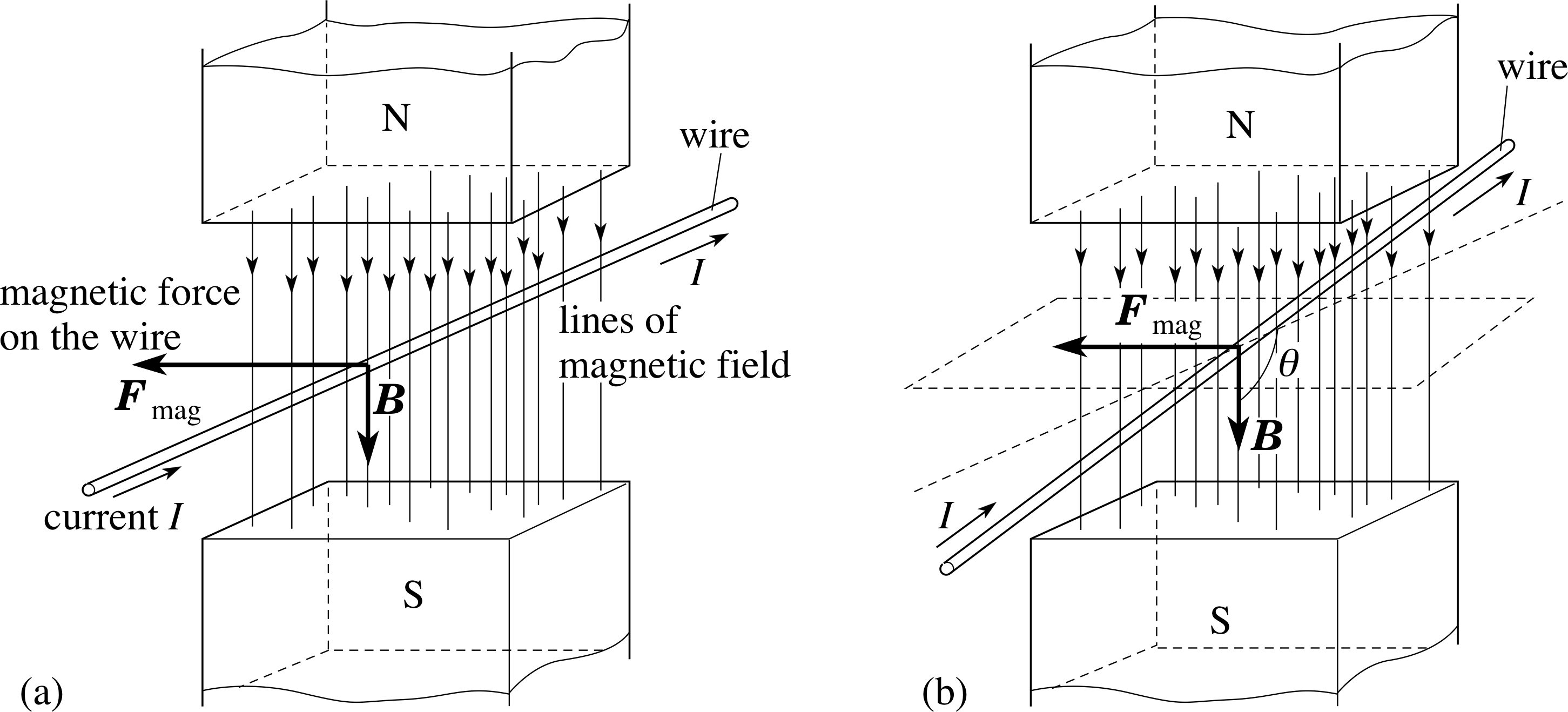
Figure 1 A current in a magnetic field gives rise to a force: (a) with the current and magnetic field at 90°, (b) with the current and magnetic field at an angle θ. (Strictly, in the diagram the whole wire should be located in the magnetic field, otherwise the length of wire l, in the magnetic field will be different between (a) and (b).)
This information may be summarized algebraically by Equation 1:
Fmag = IlB sin θ 0 ≤ θ < 180°(1) i
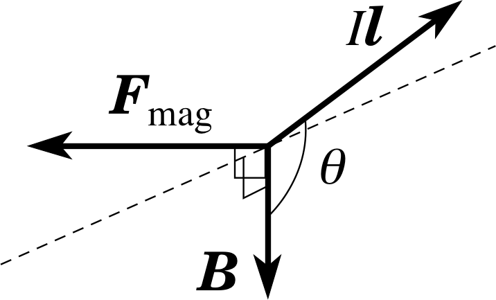
Figure 2 The corkscrew rule, as applied to the vectors representing the situation shown in Figure 1b. B and Il are in a plane perpendicular to F.
Equation 1 is consistent with the conclusions 2 to 4 and part of 6 (concerning the magnitude of the force).
Conclusions 1, 5 and some of 6 (concerning the direction of the force) require some further statement about direction.
The direction of the force can be described in terms of a corkscrew rule, as follows. If the magnetic field is represented in magnitude and direction by the vector B and we use the vector Il to represent the current I in the wire of length l, with its direction given by the flow of conventional current, i we can draw the vectors B and Il, joined at the tails, as in Figure 2. The direction of the force is then given by the direction of movement of the tip of a corkscrew, when the handle is turned from the direction of Il to the direction of B, through the smaller angle, θ. i
Using Equation 1, together with the corkscrew rule above, amounts to defining the magnetic force Fmag as the vector product or cross product of the vectors Il and B. In full vector notation we can write this as:
Fmag = Il × B(2)
In general terms, the vector product (or cross product) a × b of two vectors a and b, is a third vector c = a × b
with the properties i:
- 1
-
| c | = | a | | b |sin θ where θ is the smaller of the angles between a and b, i.e. c = ab sin θ.
- 2
-
The direction of c is given by the corkscrew rule as the direction in which the tip of a corkscrew would advance if its handle were turned from the direction of the first vector, a, to the direction of the second vector b, through the smaller angle, θ, between a and b.
Note that when this general definition of the vector product is applied to the case of Equation 2 we automatically obtain Equation 1. In other words, Fmag = Il × B implies that the magnitude of Fmag is given by Fmag = | Fmag | = IlB sin θ, as well as implying the correct direction for Fmag.
The SI unit for magnetic field strength, defined by Equation 1 is called the tesla, T: i
1 unit of magnetic field strength = 1 T = 1 N A−1 m−1
Question T1
A straight portion of wire, 15 cm long, carrying a current of 2 A at right angles to a uniform magnetic field, experiences a force of 0.04 N. Find the magnetic field strength.
Answer T1
The magnetic field strength is found from Equation 1,
Fmag = IlB sin θ 0 ≤ θ < 180°(Eqn 1)
B = Fmag/Il = 0.04 N/(2 A × 0.15 m) = 0.13 N A−1 m−1 = 0.13 T
Question T2
A wire of length 0.75 m lies along the z–axis and carries a current of 4 A in the positive z–direction. A uniform magnetic field throughout the region, has components Bx = 0.2 T, By = 0.4 T, Bz = 0.6 T. Which components of B influence the force on the wire? Find the components of this magnetic force and hence the resultant force.
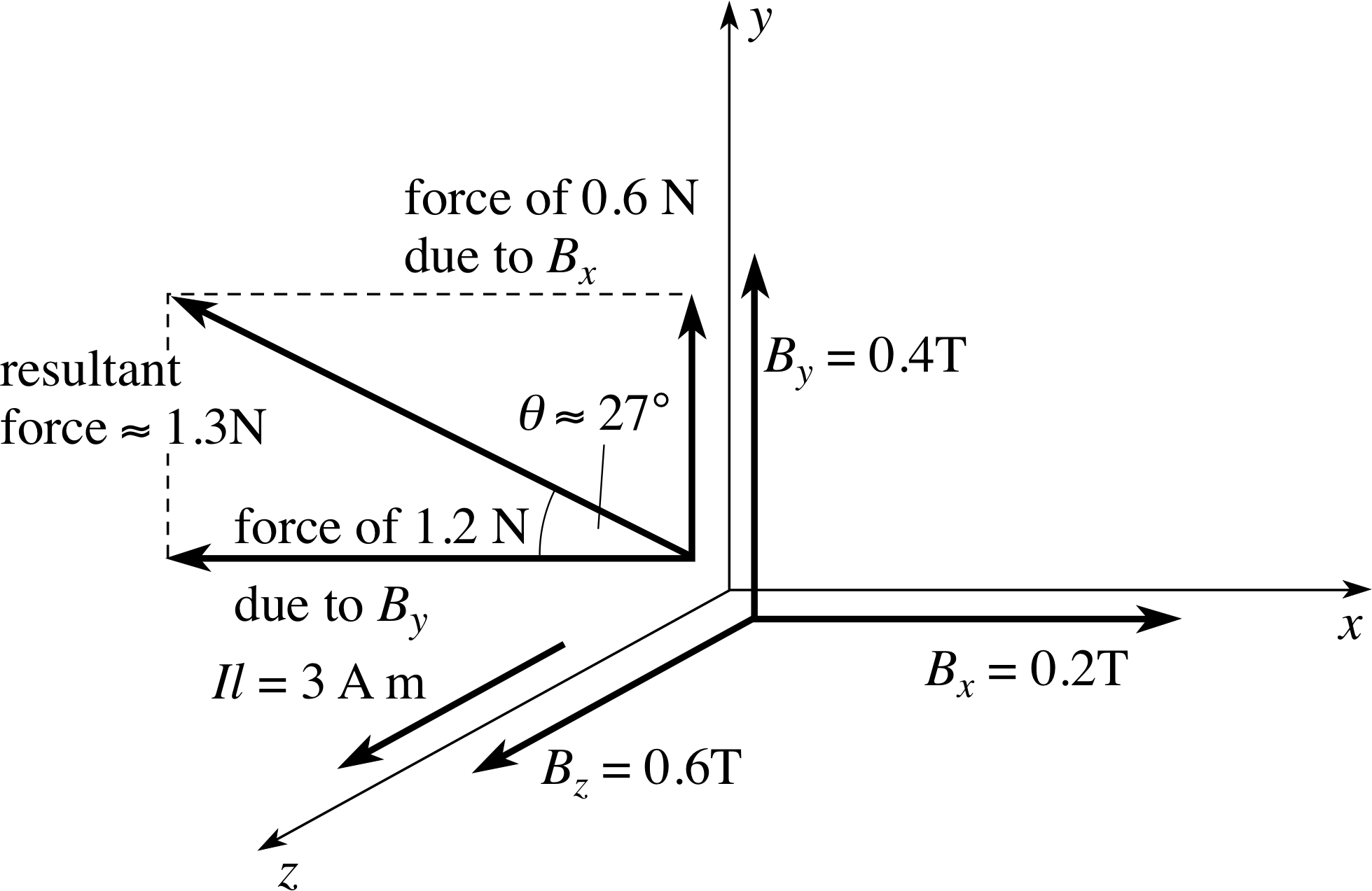
Figure 25 See Answer T2.
Answer T2
Like any other vector, B can be described by its components. Components Bx and By influence the force, but there is no contribution from Bz since it is measured along a direction parallel to the current. Since Bx is measured along a direction at right angles to the current, Equation 1,
Fmag = IlB sin θ 0 ≤ θ < 180°(Eqn 1)
shows that it produces a force of magnitude 4 A × 0.75 m × 0.2 T = 0.6 N. The force is at 90° to both the current and the magnetic field, i.e. in the y–direction. Using the corkscrew rule, the resultant force is along the positive y–direction.
Similarly, By determines a force of magnitude 1.2 N, this time along the negative x–direction. The resultant force is the vector sum of the two component vectors as shown in Figure 25. Its magnitude is $\rm \sqrt{0.6^2 + 1.2^2}\,N \approx 1.3\,N$. The angle θ between the resultant force and the x–axis has tan θ = 0.5, so θ ≈ 27°.
2.2 The magnetic torque on a coil carrying a current
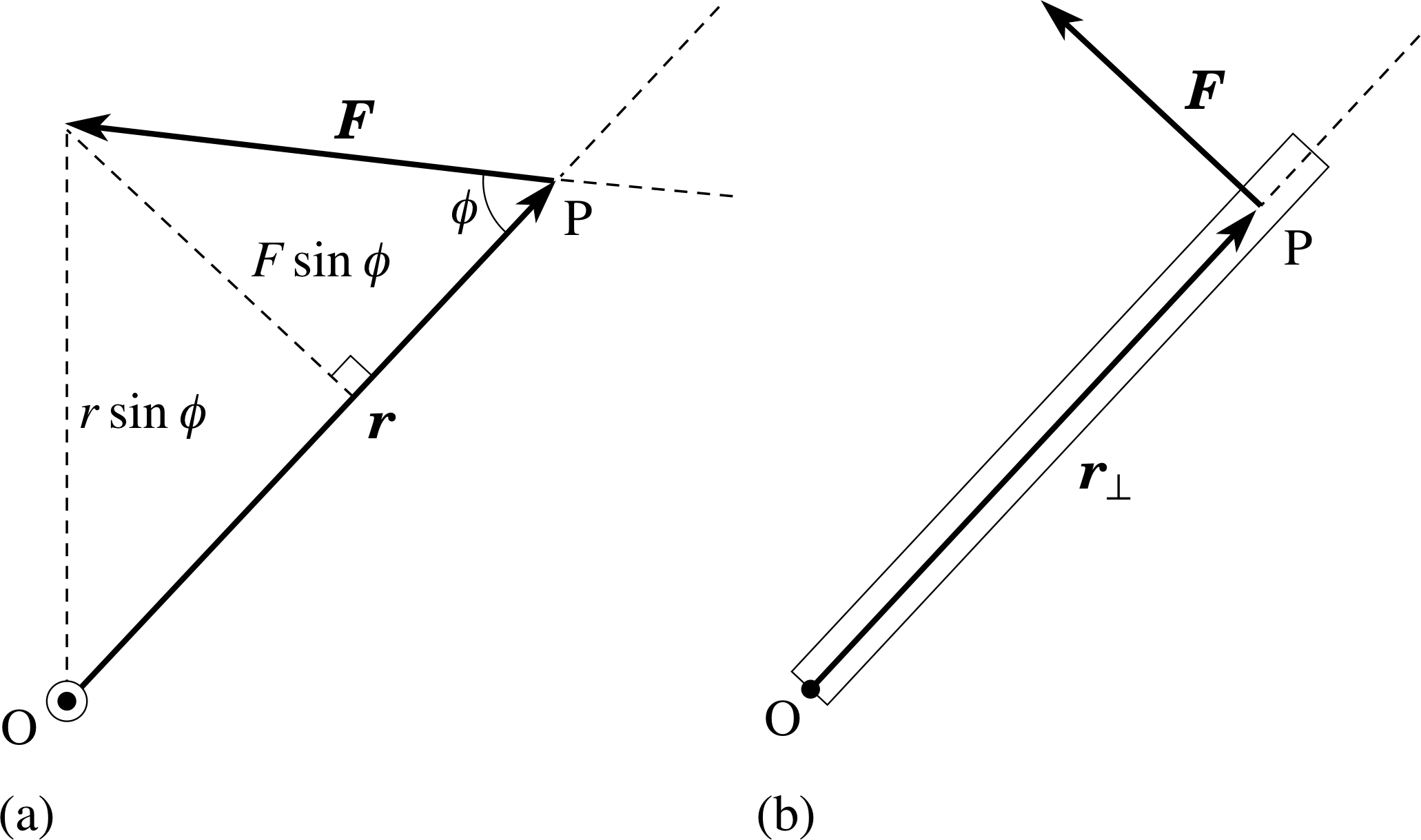
Figure 3 (a) The turning effect or torque about O produced by a force F applied at displacement r from O. The plane containing the vectors r and F is shown and ϕ is the smaller angle between these two vectors. (b) Closing a heavy door with the optimum position and angle of an applied force.
The magnetic forces on a current carrying coil may be arranged to make the coil rotate – this effect is exploited in electric motors and meters. The turning effect of a force about an axis is called its torque and arises when the line of action of the force does not pass through the axis. i A torque applied to a body will change its rotational motion, in just the same way that a force applied to a body will change its translational motion. The size of a torque depends on the magnitude of the force and the perpendicular distance between the line of action of the force and the axis in question. Torque is a vector quantity, defined by Γ = r × F (see Figure 3a), i but in this module we will be concerned mainly with its magnitude, represented by Γ, which is given by:
torque magnitude: Γ = rF sin ϕ(3) i
Equation 3 is in accord with common experience, since it implies that the turning effect is greatest when ϕ = 90°. For example, a heavy door is most easily closed if the force is applied as far as possible from the hinge and perpendicular to the face of the door, as in Figure 3b. In contrast, if the line of action of the force were to pass through the hinge (at O) then the door could not be closed, however large the force.
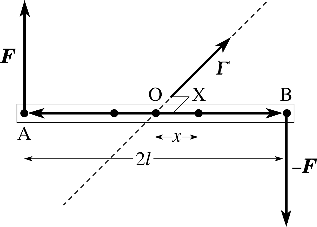
Figure 4 A rod which is free to move is acted upon by two balanced forces whose torques are additive. This constitutes a couple..
A torque about a given axis of rotation is sometimes referred to as the moment of a force about that axis. Frequently several such moments due to different forces acting in the same plane must be combined to determine the overall turning effect of the forces about an axis perpendicular to their common plane. In such situations it is possible to avoid using vector notation provided we take account of the fact that each individual moment has an associated sense of rotation about the given axis. Viewed from a fixed position above or below the plane, the sense of rotation associated with each of the moments may be described as clockwise or anticlockwise. i In calculations this sense of rotation can be indicated by associating an appropriate sign (conventionally + for anticlockwise and − for clockwise) with the magnitude of each moment. The combined effect of the moments is then indicated by the algebraic sum of these signed scalar quantities. This procedure is equivalent to adding together the various torque components perpendicular to the plane.
If we wish to produce a pure rotation of a body, without translational acceleration of the whole body, we must arrange for several forces to act such that the resultant force is zero but the resultant torque about the body’s centre of mass is not zero. The simplest case arises for two ‘equal but opposite’ forces, applied as shown in Figure 4. Such a pair of equal and opposite forces constitutes a couple acting on the rod; an example of a couple is when we turn the steering wheel of a car.
✦ From Figure 4, calculate the magnitude of the total torque about an axis perpendicular to the rod and passing through (a) point A; (b) point B; (c) point O; (d) point X.
✧ (a) and (b) About the axis through A or B, one force passes through the axis and the other force has a perpendicular distance of 2l and so the magnitude of the total torque is 2Fl.
(c) About the axis through O each force has a perpendicular distance of l, giving a torque of magnitude Fl, and since the two torques would produce the same sense of rotation the total torque has magnitude 2Fl. (d) About the axis through X one force has a perpendicular distance of l + x, giving a torque F (l + x), and the other force has a perpendicular distance of l − x, giving a torque F (l − x). The two torques would give the same sense of rotation and so the magnitude of the total torque is still 2Fl.
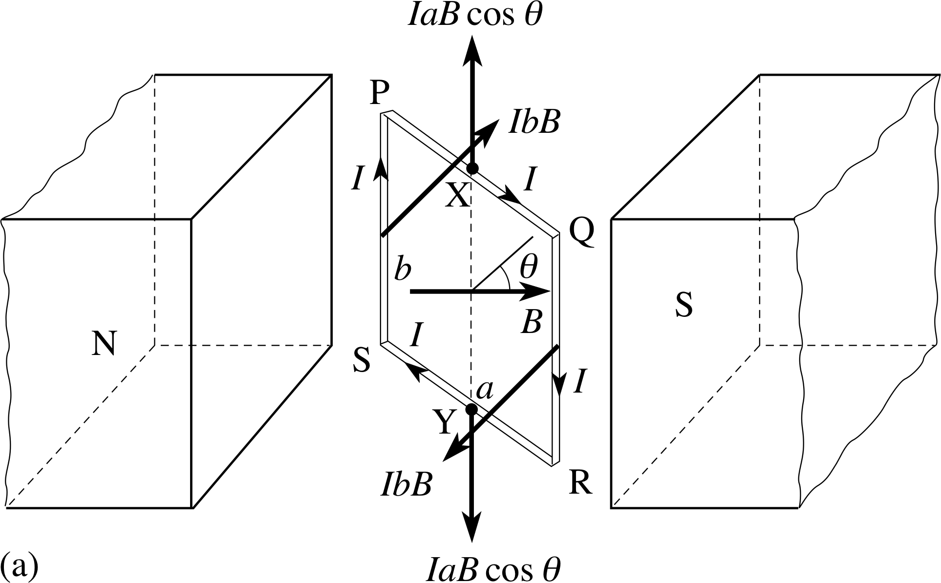
Figure 5a A rectangular coil with at an angle θ to a uniform
We will now consider the forces produced by a magnetic field on the rectangular coil PQRS, of dimensions a and b, shown in Figure 5a. The coil carries a current I, and its instantaneous orientation may be described by the angle θ between the magnetic field B and a ‘normal’ drawn perpendicular to the plane of the coil. The sections SP and QR of the loop (current at 90° to the field) will each experience a magnetic force of magnitude IbB, directed as shown. The sections PQ and RS of the loop (current at (90° − θ) to the field) will each experience a magnetic force of magnitude IaB cos θ, directed vertically, as shown.
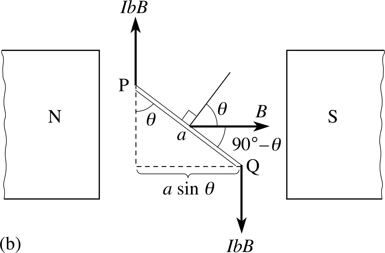
Figure 5b The couple on the coil. Note that the forces on the vertical sides of the coil are perpendicular to the field.
Figure 5b shows this in plan view. It is apparent that the forces on PQ and RS are also opposites and have the same line of action; together their only effect may be to stretch the coil slightly. The forces on SP and QR are also opposites but their lines of action are displaced; together they constitute a couple and exert a torque on the coil about a vertical axis XY through the centre of the coil. This torque will tend to rotate the coil, unless its plane is already perpendicular to the magnetic field (θ = 0), in which case the forces on SP and QR have the same line of action and give no torque.
When the normal to the coil makes an angle θ with the field, the magnitude of the total magnetic torque about the axis XY, caused by the two forces IbB, each at a perpendicular distance of (a sin θ)/2 from the axis, is:
Γmag = 2IbB (a sin θ)/2 = IBab sin θ 0° ≤ θ ≤ 180°(4)
This can also be written as:
Γmag = IBA sin θ 0° ≤ θ ≤ 180°(5)
where A = ab, the area of the coil.
Although the proof lies beyond this module, Equation 5 can be shown to apply to all coil shapes, not just rectangular ones. If the coil has N identical turns, each of area A, each loop experiences this same torque and the total torque is increased by a factor N:
Γmag = IBNA sin θ 0° ≤ θ ≤ 180°(6)
NA is sometimes called the effective area of the coil.
The expression in Equation 6 is often presented in a slightly different form that emphasizes its magnetic origin even more strongly. This is achieved by regarding the current carrying coil in Figure 5 as a source of magnetic field.
The magnetic field of a current carrying coil is very similar (b) to that of a small bar magnet and both fields (or their IbB sources) can be characterized by a quantity known as the magnetic dipole moment, μ, that may be measured in joules per tesla (J T−1). i
If the pivoted coil was replaced by a pivoted bar magnet of magnetic moment μ, located at the centre of the coil and oriented along the line perpendicular to the plane of the coil, then we would find that the magnitude of the torque on the magnet would be
Γmag = μB sin θ
Comparing this with Equation 6 we see that the pivoted coil behaves as though it has a magnetic dipole moment μ = NIA. Thus we can say:
A coil of area A and N turns, carrying a current I:
has magnetic dipole moment: μ = INA(7) i
and experiences a magnetic torque of magnitude
Γmag = μB sin θ(8)
when its normal is oriented at an angle θ to a uniform magnetic field of magnitude B.
Notice that the torque is determined by the dipole moment of the coil (or current loop), the magnetic field and by the alignment angle θ.
Question T3
What is the magnetic dipole moment of a circular coil, with 10 turns of 51 cm radius, carrying a current of 31 A? Find the maximum torque magnitude on the coil in a uniform magnetic field of 0.06 T.
Answer T3
From Equation 7,
magnetic dipole moment: μ = INA(Eqn 7)
and using the fact that 1 T = 1 N A−1 m−1 we have:
μ = INA = 3 A × 10 × π (0.05 m)2 = 0.24 A m2 = 0.24 N m T−1
Using Equation 6,
Γmag = IBNA sin θ 0° ≤ θ ≤ 180°(Eqn 6)
with θ = 90° and therefore sin θ = 1 to give the maximum torque, we have
Γmag = IBNA = μB = 0.24 N m T−1 × 0.06 T = 1.4 × 10⁻² N m
If the coil in Figure 5a is free to rotate about the vertical axis XY and is released from the position shown in Figure 5a, it will turn towards a position where its plane is at 90° to the field direction and where there is no longer a torque. However, the inertia of the coil may cause it to continue rotating beyond that position – if it does so, the magnetic torque then acts in the opposite direction, slowing it down and reversing its motion. The coil will therefore swing back and forth for a while, with friction eventually bringing it to rest with its plane at 90° to the field.
2.3 Some applications of magnetic forces: motors and meters
Simple d.c. electric motor
Figure 6 A simple d.c. motor. i
A motor is a device that provides a torque in a fixed direction. A current carrying coil in a uniform magnetic field does not meet this requirement but it comes close. To turn it into a motor we must reverse the direction of either the magnetic field or the current, each time the coil moves through its mid position (θ = 0° or θ = 180°). If the field is produced by a magnet it is usually easier to change the direction of the current rather than the field.
Figure 6 shows a system of sliding contacts which ensures that the torque is always in the same direction, but prevents the wires becoming twisted as they would if they were fixed to a rotating coil.
Each end of the wire that makes up the coil is attached to a metal collar shaped like half a ring. The two collars (together called a split ring) are separated by a small gap and rotate with the coil.
As the coil turns, the collars slide against two fixed electrical contacts, called brushes, which connect the coil to the power supply. The combination of split ring and brushes is called a commutator. If the gap is oriented as in Figure 6, then the current will be reversed whenever the coil passes through its mid position and the torque will continue to act in the same direction.
With this simple commutator the torque varies with the angle of the coil, as can be seen from Equation 8,
Γmag = μB sin θ(Eqn 8)
This would be a poor design for an electric motor. A torque which is almost independent of angle may be obtained by having many coils on the same axis, distributed at different angles, with a multi–segmented commutator feeding the current to the successive coils, with each coil connected for only a small part of the rotation.
Question T4
Sketch a graph to show how the magnitude of the magnetic torque in a single–coil d.c. motor changes as the coil rotates.
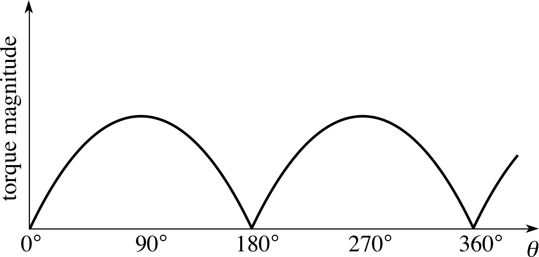
Figure 26 See Answer T4.
Answer T4
The graph is shown in Figure 26. Equation 6,
Γmag = IBNA sin θ 0° ≤ θ ≤ 180°(Eqn 6)
shows how the torque magnitude would depend on θ for 0° ≤ θ ≤ 180°. For larger values of θ the magnitude must still be positive so:
Γmag = IBNA | sin θ |
Simple a.c. electric motor
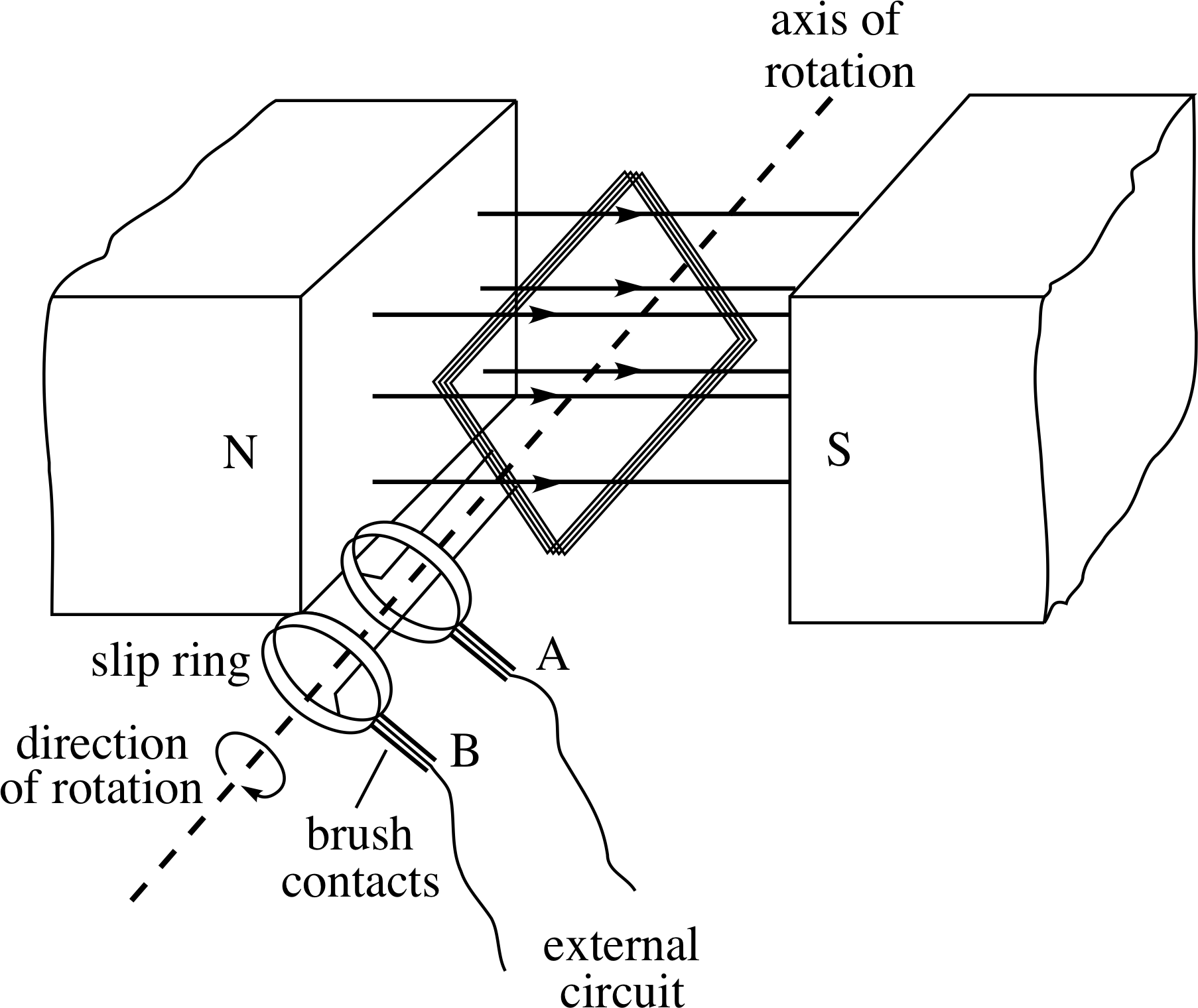
Figure 7 A simple a.c. motor.
The direction reversal already present in an alternating current can be exploited to make a simple a.c. motor. i The frequency and phase of the a.c. supply need to match the rotation of the coil so that the reversal of current always occurs when the coil is in its mid position. Sliding contacts still connect the voltage supply to the coil, to avoid twisting the wires, but now the contact is made via two separate complete rings as in Figure 7.
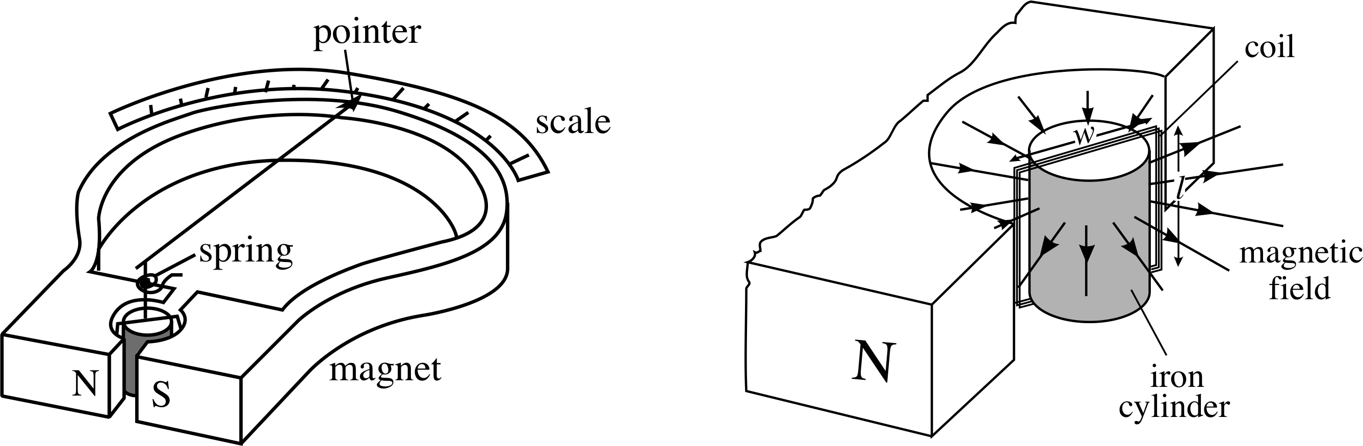
Figure 8 A moving–coil galvanometer.
Figure 8 shows a moving–coil galvanometer (MCG), with which currents or voltages may be measured. The set–up is essentially that of Figure 5, but with some modifications. Τhere is a pointer attached to the coil which is wound on a soft iron core i and is attached to a flat spiral spring, providing an opposite torque on the coil. The poles of the magnet are hollowed out so that a uniform radially–directed field is created within the gap and across the coil. These modifications are designed to produce a measurable angular deflection of the coil which is linearly proportional to the current in the coil.
Suppose the spring holds the coil with the pointer at the centre of the scale when there is no current. A current in the coil will produce a torque so that the coil turns. As it turns it will meet an increasing opposing torque from the spring. The spring is chosen so that if it is twisted through a (positive) angle α, an opposing torque Γs, of magnitude Cα, (i.e. linear in α) is produced i; so
Γs = Cα(9)
At equilibrium, Γs is equal and opposite to the magnetic torque Γmag, implying that their magnitudes are equal.
Equation 6 shows that the magnetic torque is directly proportional to the current and also depends on the angle between the coil and the magnetic field. With the uniform radially–directed field the plane of the coil lies along the field direction (θ = 90°), irrespective of the angle α through which the coil has turned, so the magnetic force on each side of the coil is constant and always at right angles to the plane of the coil. Equation 6,
Γmag = IBNA sin θ 0° ≤ θ ≤ 180°(Eqn 6)
then gives:
Γmag = IBNA(10)
✦ Use Equations 9 and 10 to derive the equilibrium condition when a current I flows in the coil.
✧ At equilibrium there is no net torque acting and so Γmag = −Γs, hence, taking magnitudes Γmag = Γs, so Cα = IBNA, i.e.
$\alpha = \dfrac{IBNA}{C}$(11) i
C so the deflection α is directly proportional to the current I, the scale of the meter will be linear, and therefore both accurate and easy to read.
Question T5
A galvanometer coil has 20 rectangular turns, each 1 cm by 2 cm. It can rotate about a central vertical axis in a radial magnetic field of 0.015 T, and a spring with C = 1.2 × 10⁻⁴ N m rad−1 resists its rotation. What current will produce a deflection of 22°?
Answer T5
Rearranging Equation 11,
$\alpha = \dfrac{IBNA}{C}$(Eqn 11)
and remembering that 1 T = 1 N A−1 m−1 we have:
$I = \dfrac{C\alpha}{BNA\os} = \rm \dfrac{1.2\times10^{-4}\,N\,m\,rad^{-1}\times22°\times\pi\,rad}{0.015\,N\,A^{-1}\,m^{-1}\times20\times2\times10^{-2}\,m \times1\times10^{-2}m\times180°} = 0.77\,A$
2.4 Forces between currents and the definition of the ampere
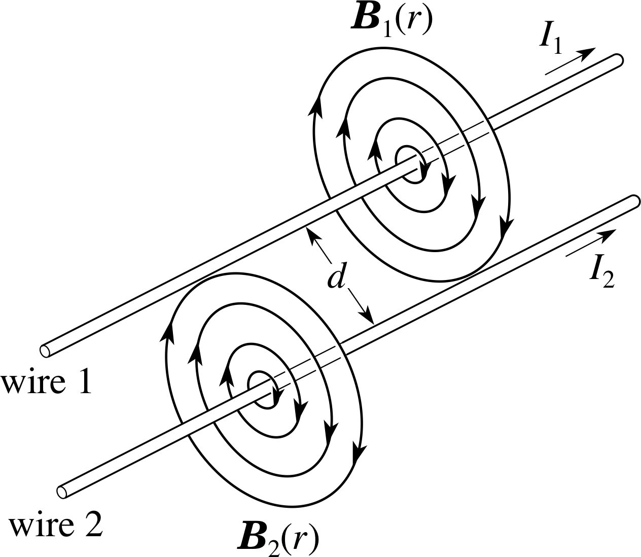
Figure 9 The magnetic fields produced by the currents in two long straight parallel wires.
We have just seen that a current carrying conductor may experience a force when in a magnetic field. Also, we know that a current generates a magnetic field. Putting these two facts together leads to the conclusion that if we have, for example, several current carrying wires, then each current will produce a magnetic field which may produce a force on the other wires. This phenomenon has important applications.
Consider the arrangement shown in Figure 9 – two long straight current carrying wires, parallel to one another. i Each wire will produce a magnetic field at the location of the other wire and so will give rise to forces on the current in that wire.
The magnetic field lines arising from the currents in each wire form a set of concentric circles around each of the wires, the direction of the field lines being given by the right–hand grip rule. The field strength at a radial distance r from wire 1, produced by the current I1 in wire 1 is:
$B_1(r) = \dfrac{\mu_0I_1}{2\pi r}$(12)
where μ0 is the permeability of free space. (See the Glossary for details.)
Since the wires are parallel, all points on wire 2 are at the same radial distance d from wire 1. The magnetic field produced by I1 has the same magnitude at every point on wire 2 and, moreover, always points in a direction perpendicular to I2. This means that the field strength at wire 2, produced by I1 is given by
$B_1(r) = \dfrac{\mu_0I_1}{2\pi d}$
The magnitude of the force F2 acting on a length l of wire 2 is then given by Equation 1,
Fmag = IlB sin θ 0 ≤ θ < 180°(Eqn 1) i
as$F_2 = I_2lB_1(d) = \dfrac{\mu_0I_1I_2l}{2\pi d}$(13)
This same final expression would have been obtained had we worked out B2(d) and F1, so the magnitude of the force per unit length on either wire is
force magnitude per unit length on wire $F = \dfrac{\mu_0I_1I_2}{2\pi d}$(14)
So much for the magnitude of these forces, but what about their directions?
✦ Use the corkscrew rule to find the direction of the force on wire 2 due to I1, and the direction of the force on wire 1 due to I2.
✧ With the currents in the same direction as in Figure 9, the force on wire 1, is directed towards wire 2, and the force on wire 2 is directed towards wire 1, i.e. the wires attract one another. The general conclusion here is, of course, consistent with Newton’s third law of motion – when two bodies interact, the force on one is equal in magnitude but opposite in direction to the force on the other.
✦ What happens if the direction of one of the currents is reversed?
✧ If the direction of, say, I1 is reversed, then the force on wire 1 is reversed because it is still in the same field from wire 2. The force on wire 1 is therefore directed away from wire 2. The field that I1 produces is also reversed, while I2 is unchanged, so the force on wire 2 is also reversed. Thus, the force on wire 2 is directed away from wire 1. The wires now repel one another.
All this may be summarized by the rule:
Like currents attract, unlike currents repel. i
Question T6
A large current flows in a circular path within an ionized gas (called a plasma). Explain whether such a current loop could be stable or whether there would be a tendency for it to collapse inwards or expand outwards, due to the mutual magnetic forces.
Answer T6
Whilst it would be mathematically difficult to calculate the forces, it is predictable that there would be a tendency for such a current loop to expand outwards, due to the mutual magnetic forces. You can see this if you imagine the forces between any section of the current and the section diametrically opposite to it, on the other side of the loop. The currents in these sections are in opposite directions and so there is mutual repulsion between them. Since this is true for each section of the current loop it must be true of the overall loop, which will tend to expand outwards under this force. This example illustrates one of the problems faced in plasma physics!
Equation 14 provides a definition of the basic SI electrical unit in terms of the basic mechanical units of force and distance. This basic electrical unit is that of electric current and is called the ampere. i
Given two infinitely long straight, parallel wires, set 1 metre apart in a vacuum and each carrying the same current, then that current is defined to be 1 ampere (1 A) if the force per metre on each wire has a magnitude of 2 × 10⁻⁷ N.
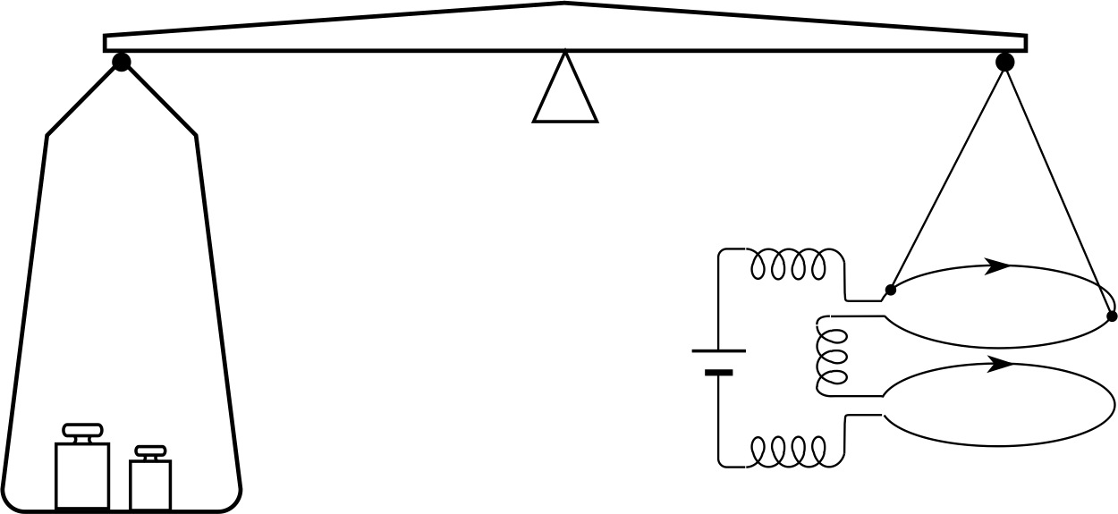
Figure 10 Schematic diagram of a current balance.
Equation 14 suggests a direct way to measure current force magnitude per unit length on wire – simply measure the force between two very long parallel wires at a known separation. Equation 14, fortunately, also gives the force per unit length between parallel equal–sized circular coils, provided their separation is much less than their radius. In the equation, l then becomes the circumference of a coil. The force between two currents can be measured using a relatively compact current balance as shown schematically in Figure 10. The scales are first balanced with no current, then a current is passed in the same direction through each coil, further weights being added to rebalance the scales against the force of attraction between the currents. Any other current meter may then be calibrated by comparing it with a current balance.
Question T7
Use Equation 14,
force magnitude per unit length on wire $F = \dfrac{\mu_0I_1I_2}{2\pi d}$(14)
and the definition of the ampere to determine the value of μ0, the permeability of free space, and its SI units.(Note that the possibility of performing such a calculation shows that μ0 is a defined quantity.)
Answer T7
Substituting I1 = I2 = 1 A, d = 1 m, F/l = 2 × 10⁻⁷ N m−1 in Equation 14 gives us μ0 = 4π ×10−7 N A−2. (Alternative (derived) units for μ0 are T m A−1 and H m−1, where H is the henry, a unit of inductance.)
3 Magnetic forces on a moving charged particle
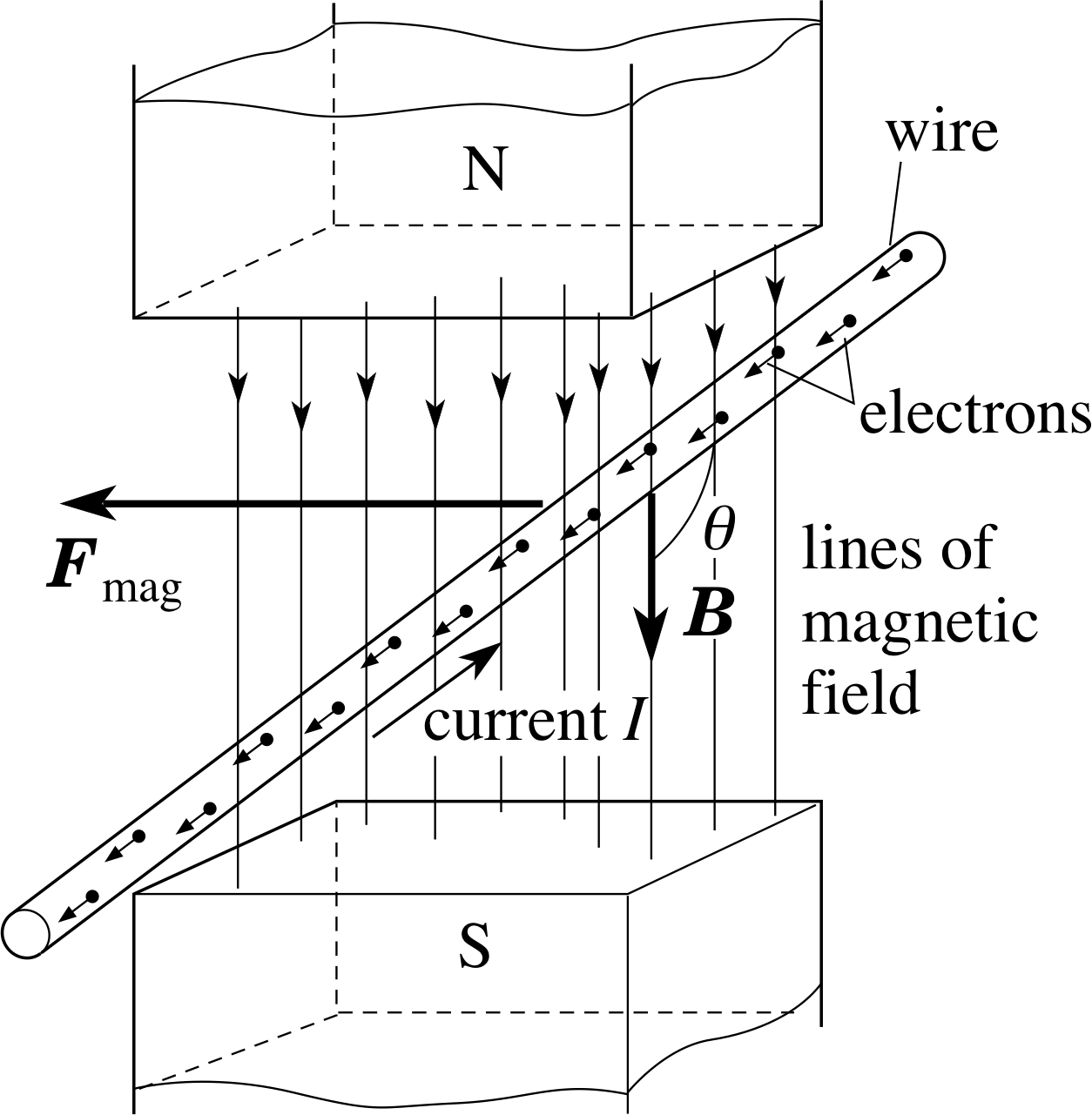
Figure 11 Electrons travelling through a wire in a magnetic field and experiencing a magnetic force.
In Section 2 we considered magnetic forces on currents, i.e. on large numbers of moving charged particles. We now turn our attention to the magnetic force on an individual moving charged particle. We will first consider an electron moving in a wire within a magnetic field and then generalize to a charged particle whose motion is unconstrained.
3.1 The magnetic force on an electron in a wire
Figure 11 shows a straight wire, carrying a current I, at an angle θ to a uniform magnetic field B. The magnitude Fmag of the magnetic force on a length l of the wire is
Fmag = IlB sin θ(Eqn 1)
From our discussions in Section 2 and knowing that current consists of a movement of charged particles, we can deduce some important characteristics of the magnetic force on a single charged particle i:
- 1
-
There is no magnetic force when there is no current, suggesting that the magnetic force acts only on charged particles that are moving.
- 2
-
The magnetic force always acts at 90° to the current, indicating that the magnetic force on a single particle acts at 90° to its direction of motion.
- 3
-
The magnitude of the magnetic force is proportional to the current, indicating that the magnitude of the magnetic force on a single particle is proportional to its speed.
- 4
-
The magnetic force depends on the angle between the field and the current, suggesting that the magnetic force depends on the particle’s direction of motion, as well as its speed, i.e. on its velocity.
To derive an expression for the magnetic force on a single charged particle within the wire, we will consider a portion of wire of length l, as shown in Figure 11. First, we need to relate the current I to the motion of the individual charged particles, which here are electrons.
The electrons are uniformly distributed throughout the wire so that there are n free electrons per unit volume of the wire. This number of electrons per unit volume is often referred to as the number density. i If there is no current in the wire, the free electrons move rapidly and randomly in the wire, colliding with the ionic lattice, but with no average motion along the wire. When a battery is connected, so that a current flows, each free electron accelerates along the wire in the time between collisions. The collisions interrupt this non–random motion, so that the net effect is that a small average drift along the wire, at a speed of υdrift, becomes superimposed on the random motion. The magnetic force on the wire then arises as a result of the magnetic force on this average drift motion of the free electrons.
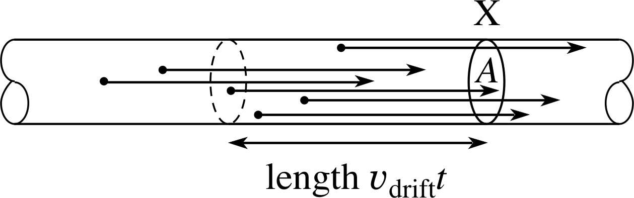
Figure 12 All the free electrons within a length υdriftt of a cross section of the wire move through that cross section in a time interval t.
The current is numerically equal to the charge flowing through a cross section of the wire per second. For a particular cross section X (area A) of the wire, as shown in Figure 12, all those electrons within a distance υdriftt to the left of X, flow past X in a time t. That is, all the electrons in the volume Aυdrift, a total of nAυdrift electrons, pass through X in one second. As each electron carries a charge of magnitude e, the numerical value of the charge flow per second, the current I, is
I = nAυdrifte(15)
The magnitude of the magnetic force on a length l of the wire is therefore:
Fmag = nAυdriftelB sin θ(16)
As our segment of wire has a volume Al, the number of free electrons in it is nAl, and we can divide Equation 16 by nAl to obtain:
The magnitude of the magnetic force on a single electron moving with speed υdrift at angle θ to a magnetic field of magnitude B:
Fmag = eυdriftB sin θ(17)
Question T8
Why is it, that in calculating the magnetic force on the electrons which make up the current in the wire, we can ignore the very large random velocities which these electrons may have?
Answer T8
If we have a very large number of electrons moving entirely randomly then there will, on average, be just as many moving in a given direction as in the opposite direction, and the net magnetic force on them all will be zero. If, however, there is a drift velocity superimposed on this random motion then there will be a net magnetic force, provided the drift velocity has some component across the magnetic field.
Question T9
The number density of free electrons in copper is 8.5 × 1028 m−3. Find the drift speed of the electrons when there is a current of 0.2 A in a copper wire of diameter 2 mm.
Answer T9
From Equation 15,
I = nAυdrifte(Eqn 15)
we have:
$\upsilon_{\rm drift} = \dfrac{I}{neA} = \rm \dfrac{0.2A}{8.5\times10^{28}\,m^{-3}\times1.6\times10^{-19}\,C\times\pi(10^{-3}\,m)^2} = 4.7\times10^{-6}\,m\,s^{-1}$
It is apparent from this calculation that these drift velocities are very small.
3.2 The magnetic force on a moving charged particle
So far we have considered only electrons, but any particle of charge q, moving with speed υ at an angle θ to a magnetic field will experience a force. We can rewrite Equation 17 for the magnitude of this force as
Fmag = | q | υB sin θ(18) i
Of course, at any point in space where the magnetic field is specified by the vector B, the magnetic force Fmag on a particle of charge q and velocity υ will have a direction as well as a magnitude. Both these aspects of the force can be determined from the vector equation
Fmag = qυ × B(19)
where υ × B is a vector product of the kind that we introduced in Subsection 2.1.
You will recall that writing such a relationship implies that:
- 1
-
Fmag = | Fmag | = | q | υB sin θ(Eqn 18)
where θ is the smaller angle between υ and B.
- 2
-
The direction of F is given by the corkscrew rule (or, equivalently, the right–hand rule) as the direction in which the tip of a corkscrew would advance if its handle were turned from the direction of the first vector (υ) to the direction of the second vector (B) through the smaller angle (θ) between them.
Equation 19 is a very important equation. It applies just as well in a non–uniform magnetic field where B varies from point to point (and is usually written B (r)) as it does in a uniform field where the magnitude and direction of B are the same at all points.
You should certainly try to remember Equation 19, but when using it you should also remember that the sign of q is important, and so is the order of the vectors in the cross product (υ × B not B × υ). If you use the wrong sign for q, or if you reverse the order of υ and B you will obtain the wrong sign (and hence the wrong direction) for Fmag. In practice, when using Equation 19, it is generally best to first apply the corkscrew (or right-hand) rule to υ × B to determine its direction, and then recognize this as either parallel or antiparallel to Fmag, according to whether q is positive or negative. Some immediate practice in using Equation 19 is in order.
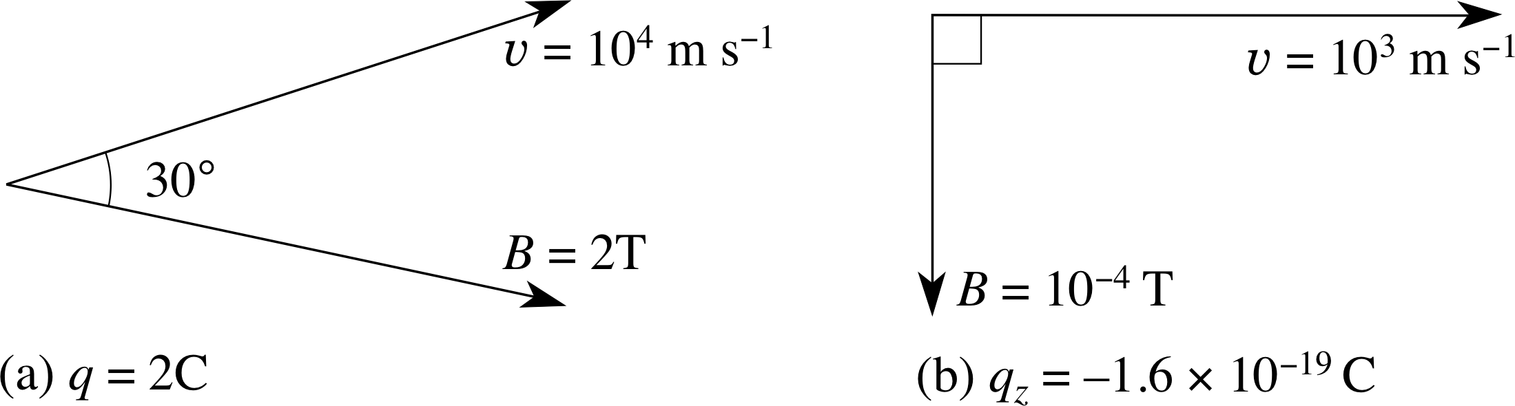
Figure 13 See Question T10.
Question T10
Find the magnitude of Fmag in Figure 13a and 13b, which show the plane containing the vectors υ and B.
Answer T10
Using Equation 18,
Fmag = | q | υB sin θ(Eqn 18)
in both cases we have:
(a) Fmag = 2 C × 104 m s−1 × 2 T × sin 30° = 2 × 10⁴ N
(b) Fmag = 1.6 × 10−19 C × 103 m s−1 × 10⁻⁴ T × sin 90° = 1.6 × 10⁻²⁰ N
Question T11
In each of the cases below, work out the directions of (i) the vectors (υ × B) and (ii) the magnetic force Fmag.
(For example, in (a) both (υ × B) and Fmag are perpendicularly out of the page.)
(a) υ→ B↑ q positive (b) υ← B↑ q positive (c) υ← B↑ q negative (d) υ zero B↑ q negative
(e) υ perpendicularly into the page B↑ q negative (f) υ↓ B perpendicularly out of the page q positive
Answer T11
Using Equation 19,
Fmag = qυ × B(Eqn 19)
and the corkscrew rule we find:
(a) As given in the question υ × B and Fmag are both perpendicularly out of the page (q is positive).
(b) υ × B and Fmag are both perpendicularly into the page (q is positive)
(c) υ × B is perpendicularly into the page but Fmag is perpendicularly out of the page (q is negative).
(d) Since υ = 0, υ × B and Fmag are both zero.
(e) υ × B is in the plane of the page, perpendicular to B and to the right, but Fmag is in the plane of the page, perpendicular to B and to the left (q is negative).
(f) υ × B and Fmag are both in the plane of the page, perpendicular to υ and to the left (q is positive).
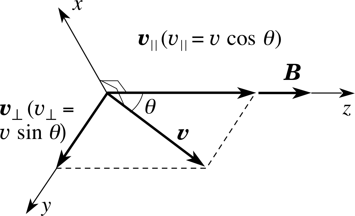
Figure 14 The component vectors of velocity parallel and perpendicular to the magnetic field B are υ| | and υ⊥. Note that υ| | = | υ| | | and υ⊥ = | υ⊥ |.
In many three–dimensional situations it is useful to associate a definite direction with the magnetic field and then to describe the velocity of a moving charged particle in relation to that held direction. i For instance, Figure 14 shows a particle with charge q and velocity υ moving through a point at which the direction of the magnetic field B has been designated as the z–direction. The velocity υ of the particle may then be resolved into two component vectors, υ| | and υ⊥ in such a way that υ| | is parallel to B (and therefore in the z–direction) while υ⊥ is perpendicular to B (and therefore in the (x, y) plane). For the particular case shown in Figure 14 the description of the velocity has been even further simplified by choosing the orientation of the x– and y–axes in such a way that υ⊥ points along the y–axis.
Using the parallel and perpendicular velocity component vectors we can write
υ = υ| | + υ⊥(20)
and substituting this into Equation 19,
Fmag = qυ × B(Eqn 19)
we obtain
Fmag = q (υ| | + υ⊥) × B = qυ| | × B + qυ⊥ × B
but notice, the term involving υ| | × B vanishes because its magnitude is υ| | B sin θ, and the angle between υ| | and B is 0°. Thus, we obtain the useful expression:
Fmag = qυ⊥ × B(21)
which shows that only the velocity component vector perpendicular to the magnetic field influences the magnetic force at any point, and that furthermore
Fmag = | Fmag | = | q | υ⊥B
since the angle between υ⊥ and B is 90° and sin 90° = 1.
Determining the magnetic field at a point
Equations 19 (and 21) provide a means of determining the magnitude and direction of any magnetic field at a point, and of deriving its units. For example, from Equation 21, when a particle of charge 1 C moves at a speed of 1 m s−1 perpendicularly to a magnetic field of strength 1 T, it experiences a magnetic force of magnitude 1 N. More generally, if a particle of charge q experiences a magnetic force F1 when it travels through a point with velocity υ1, and a magnetic force F2 when it travels through the same point with a velocity υ2 that is perpendicular to υ1 then it can be shown from Equation 19 that the magnetic field at that point is
${\bi B} = \dfrac 1q\left(\dfrac{{\bi F}_1\,{\boldsymbol {\times\,\upsilon}}_1}{\upsilon_1^2}\right) + \dfrac 1q\left(\dfrac{({\bi F}_2\,{\boldsymbol {\times\,\upsilon}}_2)\boldsymbol{\cdot}\boldsymbol{\upsilon}_1}{\upsilon_1^2\upsilon_2^2}\right)\boldsymbol{\upsilon}_1$
where the second term on the right describes the component of B in the direction of υ1, and the first term describes the component of B perpendicular to υ1. i
✦ Use Equation 21 to derive the SI units of B, and show that they are equivalent to N A−1 m−1, as derived in Subsection 2.1.
✧ From Equation 21,
B = Fmag / | q | υ⊥(Eqn 21)
so the SI units of B are N (m s−1)−1 C−1 = N s m−1 C−1. Since 1 A = 1 C s−1, we have 1 s C−1 = 1 A−1, and we have the units of B as N m−1 A−1, as found in Subsection 2.1.
3.3 Motion of a charge along or perpendicular to a uniform magnetic field
Before we consider the general motion of a charge in a magnetic field we will start by taking the special cases where the charge is moving either parallel to the field or perpendicular to the field.
Motion parallel to the field
✦ Describe what happens if the motion of a moving charge is parallel to the field or opposite (antiparallel) to the field (i.e. υ = υ⊥, with υ| | = 0).
✧ From Subsection 3.2 you should have gathered that where the initial velocity υ of the particle is either parallel to B, (θ = 0°, with the particle moving along with the field) or against the direction of the field (θ = 180°) there will be no magnetic force on the particle. It must therefore continue to move with constant velocity υ| | while υ⊥ = 0.
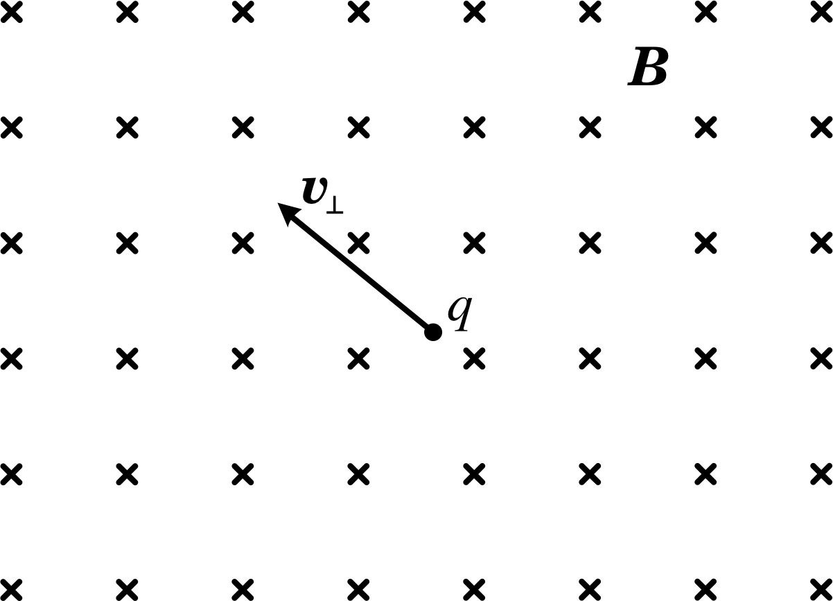
Figure 15 A uniform magnetic field directed into the page. υ⊥ is the initial velocity vector of a particle of charge q moving perpendicular to the field, in the plane of the page.
Motion perpendicular to the field: cyclotron motion
Let us now consider the situation where the initial velocity of the particle is perpendicular to the field (i.e. υ = υ⊥, with υ| | = 0). Figure 15 shows a positively charged particle moving at right angles to a uniform magnetic field. The particle has an initial velocity υ = υ⊥, in the plane of the paper, and the magnetic field lines are directed into the page. i
Question T12
On a sketch of Figure 15, show the direction of the magnetic force on the particle if the charge is positive. What will be the effect of this force on the particle’s motion? Sketch the path of the particle. How would the situation differ if the charge were negative?
Answer T12
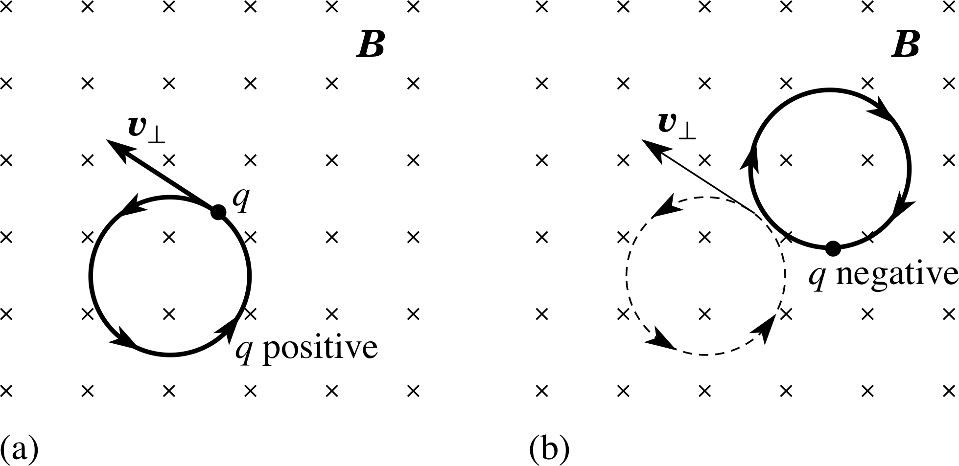
Figure 27 See Answer T12.
The force is at right angles to the velocity (downwards and rotated 90° anticlockwise from υ⊥, within the plane of the paper). This force will not change the speed of the particle, since the acceleration is perpendicular to the velocity, but it will change the direction of the velocity. As the direction of the velocity changes, so too does the direction of the magnetic force, which is always perpendicular to this velocity. It is clear then that the magnetic field will never change the speed of the particle but will provide a constant magnitude acceleration at 90° to the velocity. This situation causes the positively charged particle to move in uniform circular motion, anticlockwise in the plane of the paper, as shown in Figure 27a, with the magnetic force acting as the centripetal force towards the centre.
If the sign of the charge were reversed then the motion would be clockwise around a similar circle, centred around a position upwards and to the right of the initial position of the particle, as shown in Figure 27b.
The magnitude of the centripetal acceleration a of a particle moving in uniform circular motion with speed υ in a circular orbit of radius r is
$a = \dfrac{\upsilon^2}{r}$(22)
The centripetal force that provides this acceleration is given by Newton’s second law of motion (F = ma). In this case, that force is the magnetic force arising from the velocity component perpendicular to the field, so its magnitude is given by:
centripetal force ${\bi F}_{\rm mag} = \lvert\,q\,\rvert\upsilon_\bot{\bi B} = \dfrac{m\upsilon_\bot^2}{r}$(23)
This can be rearranged to give an expression for the radius of the circular path of the particle in the plane perpendicular to the magnetic field:
radius of path in a uniform magnetic field B, $r = \dfrac{m\upsilon_\bot}{\lvert\,q\,\rvert\,B}$(24)
Question T13
Find the speed of an electron that is moving in a circle of radius 0.30 m at 90° to a magnetic field of magnitude 10−3 T. (Electron charge e = 1.6 × 10⁻¹⁹ C, electron mass me = 9.1 × 10⁻³¹ kg.)
Answer T13
If we rearrange Equation 24,
radius of path in a uniform magnetic field B, $r = \dfrac{m\upsilon_\bot}{\lvert\,q\,\rvert\,B}$(Eqn 24)
we find:
$\upsilon_\bot = \dfrac{\lvert\,q\,\rvert\,Br}{m} = \rm \dfrac{1.6\times10^{-19}\,C\times10^{-3}\,T\times0.3\,m}{9.1\times10^{-31}\,kg} = 5.3\times10^7\,m\,s^{-1}$
This motion is called cyclotron motion, named after an early instrument, the cyclotron, which was used for accelerating charged particles. The time for the particle to complete one full orbit in the cyclotron motion is the cyclotron period and the number of orbits completed per second, is the cyclotron frequency.
In a cyclotron, particles are held in circular orbits by a magnetic field, and accelerated twice per orbit by an electric field. As they reach higher energies, they move in larger circles but maintain the same period, enabling the electric field to be applied at the same frequency throughout the process. i
Let us test this claim.
✦ Find the cyclotron period by dividing the circumference of the circle by the orbital speed.
✧ The circumference is equal to 2πr and the orbital speed is υ⊥. Using Equation 24,
radius of path in a uniform magnetic field B, $r = \dfrac{m\upsilon_\bot}{\lvert\,q\,\rvert\,B}$(Eqn 24)
we can write cyclotron period as:
cyclotron period $T_{\rm cyclotron} = \dfrac{2\pi r}{\upsilon_\bot} = \dfrac{2\pi}{\upsilon_\bot}\dfrac{m\upsilon_\bot}{\lvert\,q\,\rvert\,B} = \dfrac{2\pi m}{\lvert\,q\,\rvert\,B}$(25)
✦ Next, find the cyclotron frequency fcyclotron at which the particle circulates.
✧ By taking the reciprocal of the period, we find:
cyclotron frequency $f_{\rm cyclotron} =\dfrac{1}{T_{\rm cyclotron}} = \dfrac{\lvert\,q\,\rvert\,B}{2\pi m}$(26)
Multiplying fcyclotron by 2π gives us the cyclotron angular frequency ωcyclotron, of the motion
cyclotron angular frequency ωcyclotron = 2πfcyclotron = $\dfrac{\lvert\,q\,\rvert\,B}{m}$(27)
Equations 25, 26 and 27,
cyclotron period $T_{\rm cyclotron} = \dfrac{2\pi r}{\upsilon_\bot} = \dfrac{2\pi}{\upsilon_\bot}\dfrac{m\upsilon_\bot}{\lvert\,q\,\rvert\,B} = \dfrac{2\pi m}{\lvert\,q\,\rvert\,B}$(Eqn 25)
cyclotron frequency $f_{\rm cyclotron} =\dfrac{1}{T_{\rm cyclotron}} = \dfrac{\lvert\,q\,\rvert\,B}{2\pi m}$(Eqn 26)
all show a very important characteristic – the period, the frequency and the angular frequency are all completely independent of the speed of the particle. This result is actually not too surprising – the radius r of the circular path (and therefore its circumference) is proportional to υ⊥, but the speed of the particle in the circle is υ⊥, so that when we divide the circumference by the speed to find the period, υ⊥ disappears from the expression. i
The factors which determine the period of an orbit are the mass-to-charge ratio (m/q) and the magnetic field. Suppose there are lots of particles, all with the same value of m/q, moving in a given magnetic field. They may be travelling with many different speeds and in many different directions – those with very small υ⊥ will be moving in small circles, the fast ones in large circles – but all take exactly the same time to complete an orbit!
One final general point is interesting. Since the magnetic force acts always at right angles to the velocity, it changes only the direction, not the speed, of the particle, which therefore travels in a circular path at constant speed and with constant energy. A steady magnetic field can never increase the kinetic energy of a charged particle – an electric field is needed to do this, as we said earlier.
Question T14
(a) Verify that Equation 26 gives suitable units for frequency. (b) Find the cyclotron frequency of an electron moving in a field of 0.05 T.
Answer T14
(a) The SI units of the right–hand side of Equation 26,
cyclotron frequency $f_{\rm cyclotron} =\dfrac{1}{T_{\rm cyclotron}} = \dfrac{\lvert\,q\,\rvert\,B}{2\pi m}$(Eqn 26)
are C(N A−1 m−1) kg−1. (Don’t forget that 1 T = 1 N A−1 m−1).
If we use the following unit conversions 1 N = 1 kg m s−2 and 1 A = 1 C s−1, we can write 1 C A−1 = 1 s and 1 N m−1 kg−1 = 1 s−2. Therefore 1 C N A−1 m−1 kg−1 = 1 s−1, i.e. 1 Hz.
(b) From Equation 26:
$f_{\rm cyclotron} = \dfrac{1}{T_{\rm cyclotron}} = \dfrac{\lvert\,q\,\rvert\,B}{2\pi m} = \rm \dfrac{1.6\times10^{-19}\,C\times0.05\,T}{2\pi\times9.1\times10^{-31}\,kg} = 1.4\times10^9\,Hz$
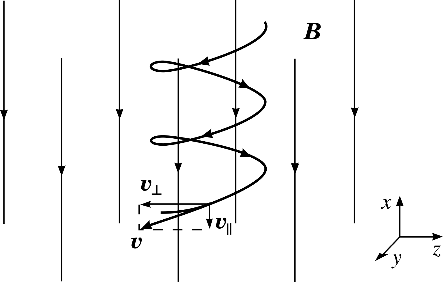
Figure 16 The helical path of a charged particle in a uniform magnetic field.
3.4 Motion in a uniform magnetic field: the general case
We can now generalize to the situation in which a charged particle moves in some arbitrary direction with respect to the field, as in Figure 16. The velocity vector can always be resolved into the two component vectors, one along and one perpendicular to the field. We then have the two situations which we have just dealt with. The component vector along the field (magnitude υ| | = υ cos θ ) is unchanged, whilst the component vector perpendicular to the field (magnitude υ⊥ = υ sin θ) rotates with a constant magnitude at the cyclotron frequency, in a plane perpendicular to the field.
Equations 23 to 27,
centripetal force ${\bi F}_{\rm mag} = \lvert\,q\,\rvert\upsilon_\bot{\bi B} = \dfrac{m\upsilon_\bot^2}{r}$(Eqn 23)
radius of path in a uniform magnetic field B, $r = \dfrac{m\upsilon_\bot}{\lvert\,q\,\rvert\,B}$(Eqn 24)
cyclotron period $T_{\rm cyclotron} = \dfrac{2\pi r}{\upsilon_\bot} = \dfrac{2\pi}{\upsilon_\bot}\dfrac{m\upsilon_\bot}{\lvert\,q\,\rvert\,B} = \dfrac{2\pi m}{\lvert\,q\,\rvert\,B}$(Eqn 25)
cyclotron frequency $f_{\rm cyclotron} =\dfrac{1}{T_{\rm cyclotron}} = \dfrac{\lvert\,q\,\rvert\,B}{2\pi m}$(Eqn 26)
cyclotron angular frequency ωcyclotron = 2πfcyclotron = $\dfrac{\lvert\,q\,\rvert\,B}{m}$(Eqn 27)
all remain valid, since they are already written in terms of υ⊥ = υ sin θ. In addition, we now need to add a constant velocity component of magnitude υ| | = υ cos θ directed along the magnetic field.
The resulting motion is the superposition of circular motion perpendicular to the field and uniform motion parallel to the field. Such a path (see Figure 16) is called a helix. i
4 The electromagnetic force
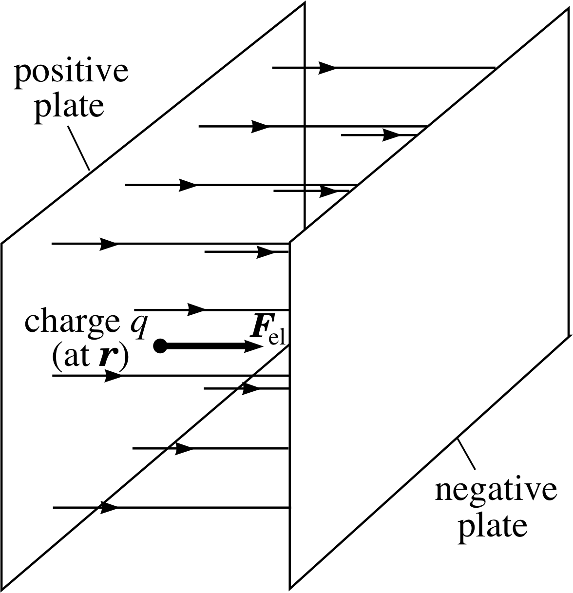
Figure 17 The electric force Fel on a charged particle in the electric field between two oppositely charged plates.
Charged particles may be influenced by electric forces and by a magnetic forces. The difference between these is that for a magnetic force to act the charge must be moving, but the electric force is independent of the motion. i The total force due to a combination of electric and magnetic fields is called the electromagnetic force; it is the sum of an electric and a magnetic force. It is this force which we will now describe.
4.1 The Lorentz force law
There are many physical situations (e.g. in an oscilloscope or a television tube) in which a particle is acted upon simultaneously by electric and magnetic forces. Figure 17 shows a charged particle in an electric field. If the charge q is at a point where the electric field is E, the electric force Fel on it is given by:
Fel = qE(28) i
Thus the direction of the electric force is parallel to the electric field if the charge q is positive, and antiparallel if it is negative.
When this electric force is added to the magnetic force, as described by Equation 19,
Fmag = qυ × B(Eqn 19)
we have the total force on the particle. If the two fields act on different parts of a particle’s path, or at different times, then the appropriate laws of force are applied separately
The total electromagnetic force on a charged particle, arising from the combined electric and magnetic forces, is known as the Lorentz force and it is expressed by the Lorentz force law: i
Lorentz force law: F = q (E + υ × B)(29)
Question T15
At a point in space there is an electric field of 104 V m−1 in the x–direction and a magnetic field of 5 × 10⁻³ T in the y–direction. An α–particle i moves in the plane containing E and B, through the point, with a velocity of 106 m s−1, at 45° to both the electric and magnetic fields. What is the net force on the particle?
Answer T15
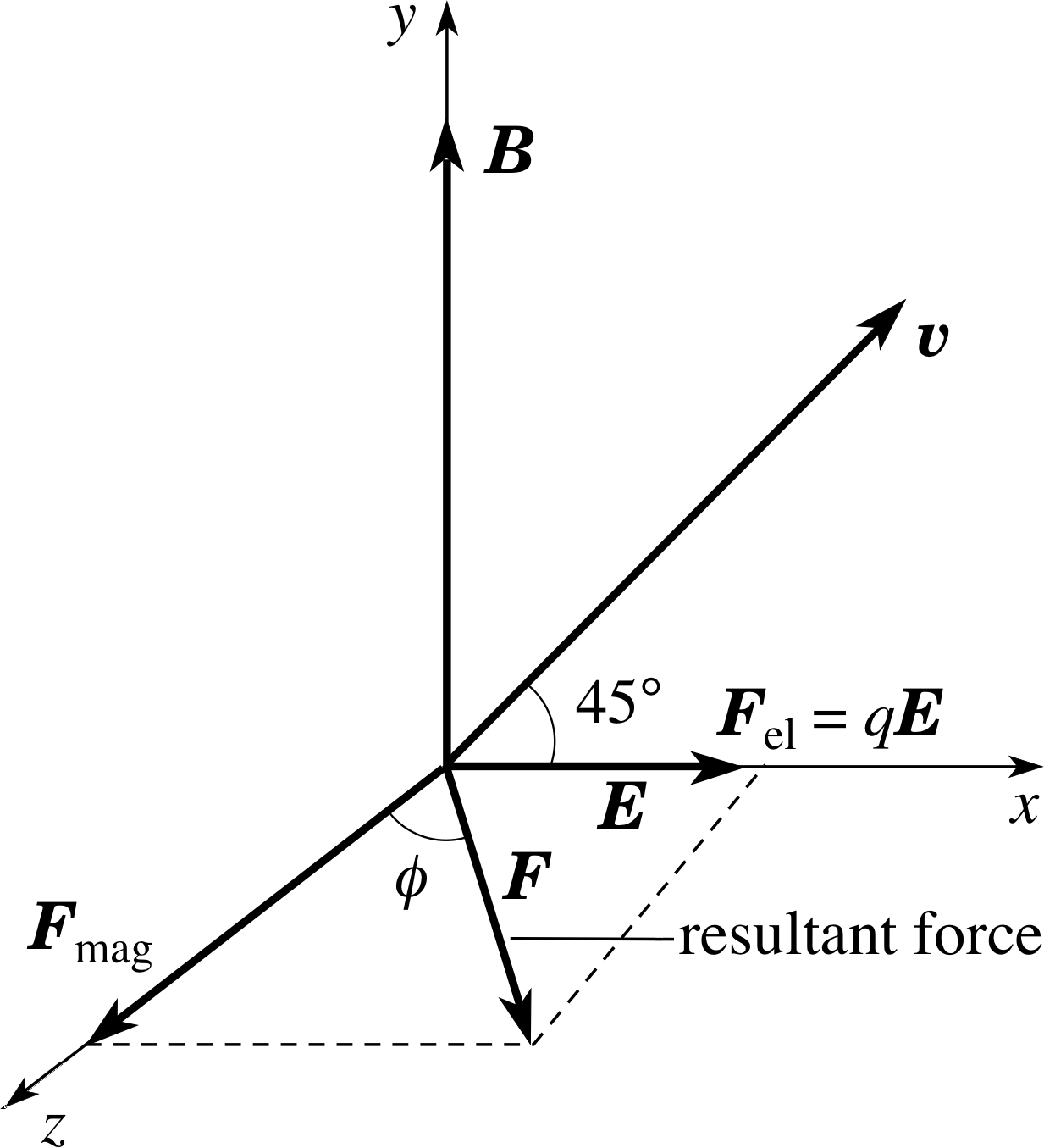
Figure 28 See Answer T15.
Figure 28 shows the directions of the E and B fields, the velocity υ of the positive α–particle, and the electric and magnetic forces acting on it. (Fmag = qυ × B) The forces are therefore of magnitude qE in the +x–direction and qυB sin 45° in the +z–direction. Their resultant has a magnitude:
F = [(qE)2 + (qυB sin 45°)2]1/2
and is at an angle ϕ to the z–direction where tan ϕ = qE/qυB sin 45°.
Hence:
F = 3.2 × 10⁻¹⁹ C[(104 V m−1)2 + (106 m s−1 × sin 45° × 5 × 10⁻³ T)2]1/2
F = 3.4 × 10⁻¹⁵ N
and
$\tan\phi = \dfrac{F_{\rm el}}{F_{\rm mag}} = \rm \dfrac{10^4\,V\,m^{-1}}{10^6\,m\,s^{-1}\times\sin\,45°\times5\times10^{-3}\,T} = 2.83$
soϕ = 70.5°
5 Some applications of the Lorentz force
The importance of the Lorentz force law, Equation 29, cannot be overemphasized. Numerous technological applications and experiments in fundamental science flow from it. In this section we will look at just a few of these, beginning with a measurement of the electron’s charge-to-mass ratio.
5.1 Measuring the charge-to-mass ratio of the electron
In Subsection 3.3 (e.g. Equation 24)
radius of path in a uniform magnetic field B, $r = \dfrac{m\upsilon_\bot}{\lvert\,q\,\rvert\,B}$(Eqn 24)
we saw that the path of a particle under the influence of a magnetic force depends on its ratio of charge-to-mass. In 1897 J. J. Thomson announced the results of a series of experiments to measure the charge-to-mass ratio for electrons. i

Figure 18 Schematic diagram of Thomson’s apparatus for e/m. The dashed line indicates the path of the undeflected beam.
This measurement was of enormous importance in the development of modern atomic theory: it demonstrated that the cathode rays formed in a gas discharge consisted of a stream of charged particles. Taken in combination with later accurate measurements of the charge on the electron i it showed the mass of an electron to be about one two–thousandth the mass of the hydrogen atom, and that the electron was a constituent part of every atom.
Thomson’s apparatus is shown schematically in Figure 18. Electrons are produced by a hot filament source and are accelerated towards twin anodes, A and D. Some electrons emerge from apertures in the anodes to form a beam which passes through a region where electric and magnetic fields may be applied. The beam strikes the fluorescent screen at the end of the tube, creating a spot of light which can be observed visually. i
In the first experiment, a known magnetic field B is applied horizontally across the electron beam, deflecting it vertically – in a direction that immediately indicates the sign of the charge on the electrons. From the deflection on the screen and the dimensions of the apparatus it is possible to calculate the radius of curvature of the beam within the magnetic field. i Equation 24 can be adapted and rearranged to relate this radius to e/me and to the electron speed υ = υ⊥. i
$\dfrac{e}{m_e} = \dfrac{\upsilon}{rB}$(30)
In the second part of the experiment, a vertical electric field E is added by applying a potential difference between the two horizontal metal plates G and H. i The electric field is arranged to give a force in the opposite direction to that produced by the magnetic field, and its strength is adjusted so as to restore the beam to its original undeflected position. The net Lorentz force on the beam is then zero, so the magnitudes of the magnetic force and the electric force are equal. We then have:
eBυ = eE(31)
or the speed required to give no deflection is:
$\upsilon = \dfrac EB$(32) i
✦ Use Equations 30 and 32 to find an expression for e/me in terms of experimentally–determined quantities.
✧ Substituting υ for the electron from Equation 32,
$\upsilon = \dfrac EB$(Eqn 32)
into Equation 30,
$\dfrac{e}{m_e} = \dfrac{\upsilon}{rB}$(Eqn 30)
we find:
$\dfrac{e}{m_{\rm e}} = \dfrac{E}{rB^2}$(33)
5.2 The velocity selector
Question T16
Suppose that in the experimental arrangement described in Subsection 5.1 the beam of particles consists not just of electrons but also neutral atoms and ions of different masses and charges, moving with a range of different speeds, but all in the same well–defined direction down the axis. If there were a small aperture on the axis, downstream of the magnetic and electric field region, describe how the beam emerging from this aperture will differ from the beam which enters the field region.
Answer T16
The geometry of the arrangment described means that only those particles which are undeflected in the field region will be able to emerge from the final aperture. The speed required to give no deflection is given by Equation 32,
$\upsilon = \dfrac EB$(Eqn 32)
This condition is independent of charge and mass; if any charged particle is undeflected by opposing electric and magnetic forces acting over the same length of path, then its speed must be given by the ratio of those fields. Only those charged particles with this particular speed, moving perpendicular to the fields, would pass undeflected. Neutral particles will of course be undeflected by the fields. So, the emerging beam along the axis will consist of all neutral atoms moving along the axis, irrespective of their speed, together with all charged particles of this particular speed, moving along the axis.
As you can see from Question T16, this device could be said to act as a velocity selector for charged particles and finds important application for this purpose.
5.3 The mass spectrometer
Equation 24,
radius of path in a uniform magnetic field B, $r = \dfrac{m\upsilon_\bot}{\lvert\,q\,\rvert\,B}$(Eqn 24)
shows that when a charged particle, such as an ion, moves in a given magnetic field, its trajectory is determined by its velocity component in the plane perpendicular to the field and by its charge-to-mass ratio. Once the charge on a particular ion is known, its trajectory in a known magnetic field allows the mass of the ion to be found. The study of ion masses and the associated atomic masses by such methods is called mass spectrometry and the instruments used are called mass spectrometers. Over the past century, mass spectrometry has made an important contribution to our understanding of matter on the atomic scale, in establishing atomic masses. It has also provided an important analytical technique for identifying unknown ions by their mass. It has been used, for example, to determine the composition and origins of meteorites and the ages of archaeological specimens. We will look at two examples of such measurements in a moment, but first we consider the design of a simple mass spectrometer.
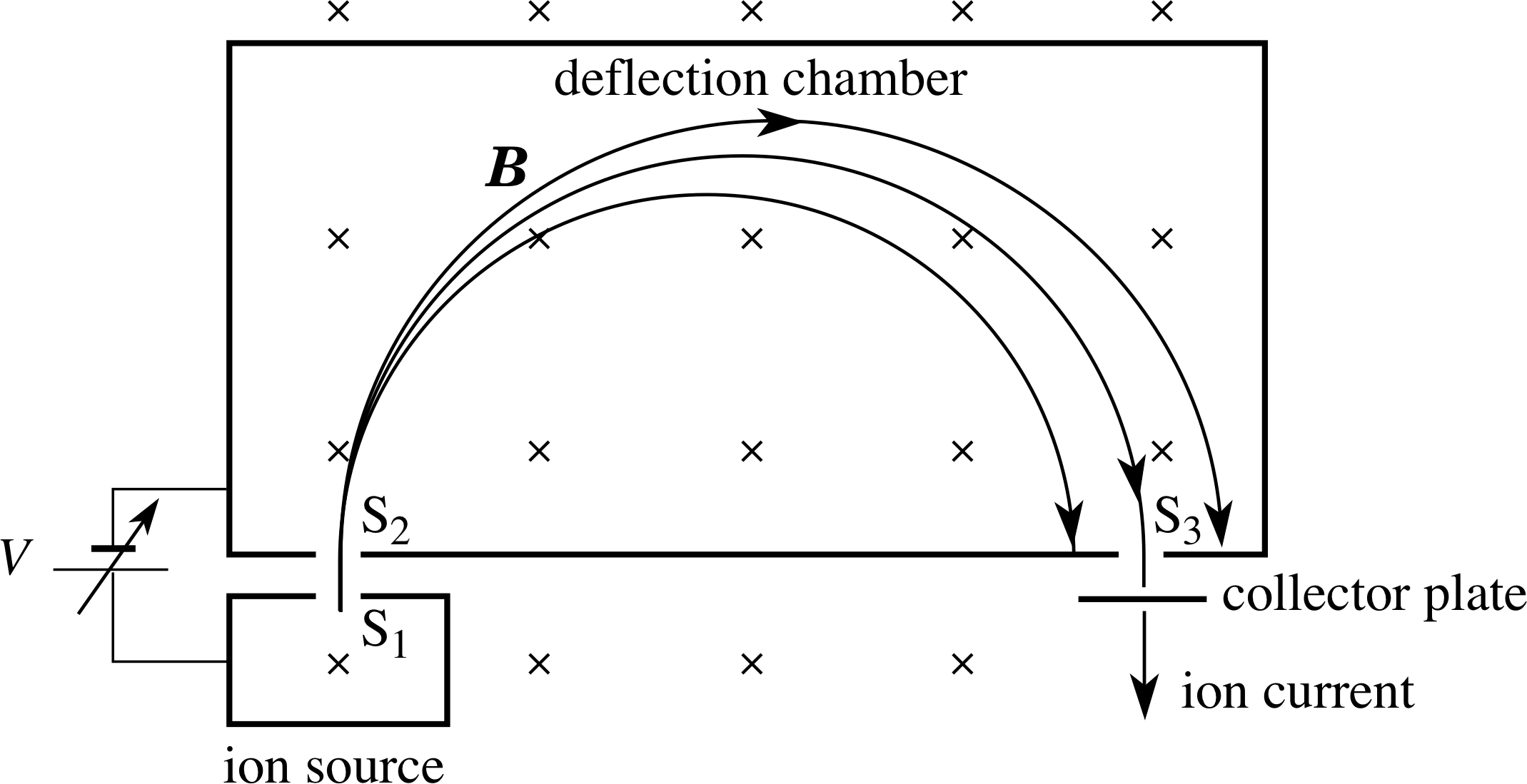
Figure 19 Schematic diagram of a Dempster mass spectrometer.
There are many designs of mass spectrometer, all of which use combinations of electric and magnetic fields. In some types, electric and magnetic fields act together, in the same region of space, and the full Lorentz force law is applicable. In others the electric and magnetic fields are separated. Figure 19 shows a design of the latter type, originally developed by Arthur Dempster (1886–1950) in 1917. In this design an electric field accelerates the ions, whilst the magnetic deflection is carried out in a region where there is no electric field. An ion source creates positive ions by bombarding the atoms in a gas with an electron beam. The electron–atom collisions strip off one or (possibly) more electrons, leaving them as ions with a net positive charge. The ions are then accelerated by the potential difference V between the slits S1 and S2. i)
On entering the chamber through S2, an ion of charge q and mass m will have a speed υ given by
$\dfrac12m\upsilon^2 = qV$
i.e.$\upsilon = \sqrt{2qV\os}{m}$(34)
Once inside the chamber a uniform magnetic field, perpendicular to the ion velocity, deflects the ions into semicircular paths with radii given by Equation 24,
radius of path in a uniform magnetic field B, $r = \dfrac{m\upsilon_\bot}{\lvert\,q\,\rvert\,B}$(Eqn 24)
Substituting for υ into Equation 24 gives us:
$r = \dfrac 1B\sqrt{\dfrac{2mV\os}{q}}$(35)
Those ions whose path diameter is equal to the distance from slit S2 to slit S3 can escape from the chamber and arrive at a collector plate, and the ion current produced at the plate is a measure of the rate of arrival of those particular ions.
The mass spectrometer can be adjusted to detect each ion in turn by changing the value of the accelerator voltage V, with B held fixed. Often this adjustment can be done automatically, to produce a mass scan across the whole mass range accessible to the instrument. The relative ion currents then give the relative concentrations of the ions in the sample.
Having discussed the theory, we will look briefly at two examples of the use of mass spectrometry.
Living biological material contains a mixture of the isotopes of carbon: mainly 12C with a small amount of radioactive 14C. i The proportions of 12C and 14C are constant in living material (as the 14C decays it is replaced from the environment) but when the organism dies, the radioactive component decreases with time. Accurate measurements of the relative proportions of the two isotopes lead to a measurement of the time since the organism died.
The relative proportions of isotopes of elements (such as 16O, 17O and 18O) in meteorites are different from the proportions found in rocks on Earth, because meteorites are formed in another part of the solar system. Accurate measurement of isotope concentrations is therefore one way to determine the origin of a rock sample.
5.4 The electromagnetic flowmeter
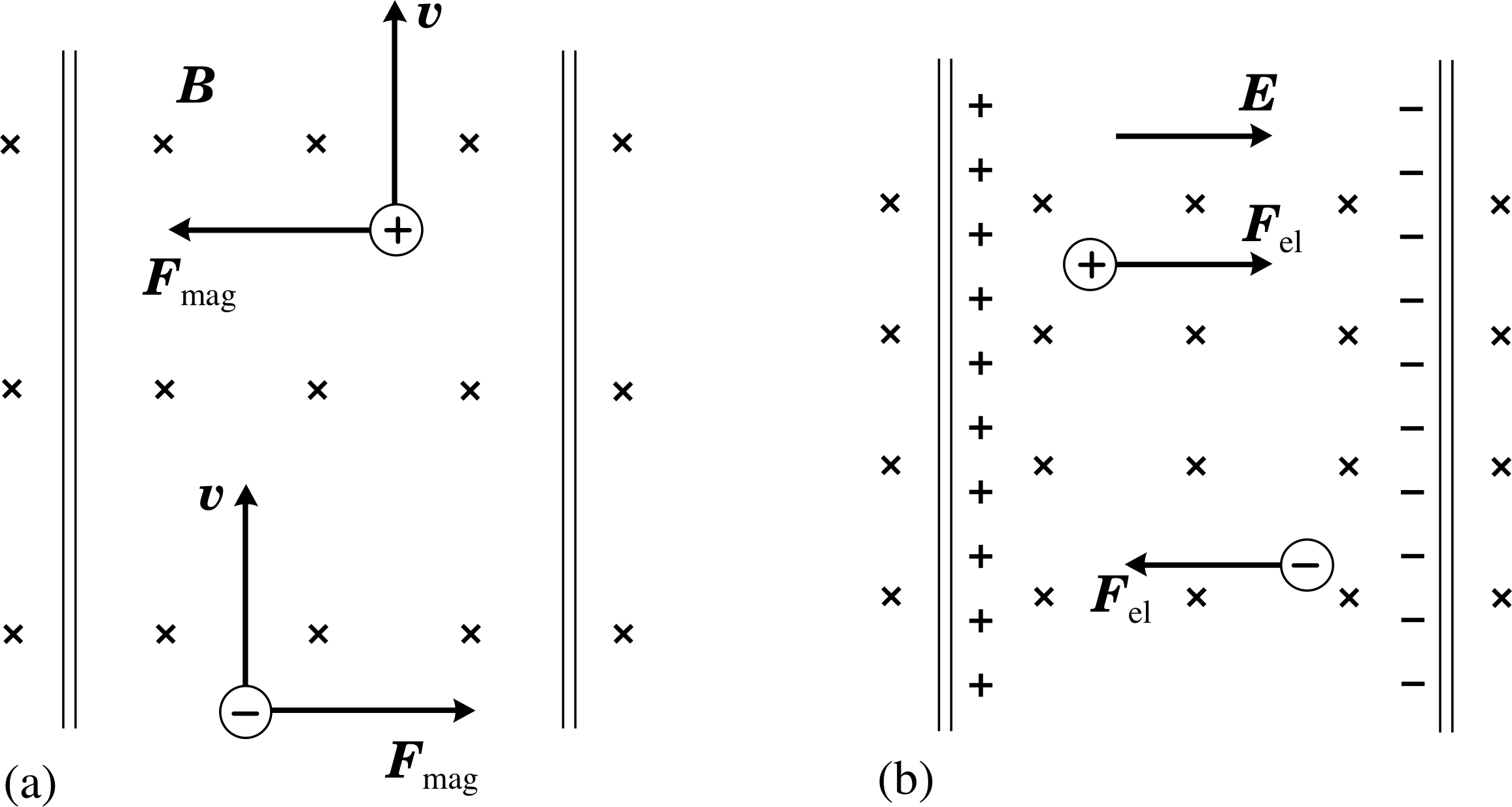
Figure 20 (a) The forces on the ions in a flowmeter. (b) The build–up of charge at the sides of the tube.
An electromagnetic flowmeter is a device that measures the flow rate of an ionic fluid. It is particularly useful in, for example, measuring rates of arterial blood flow during heart surgery because all measurements can be taken from outside the artery. Figure 20 illustrates the principle of the technique. A known magnetic field is applied across the tube (e.g. by mounting a small current carrying loop against the side of the tube), producing magnetic forces on the ions in the fluid. i The forces on the positive and negative ions are in opposite directions (Figure 20a) so the ions move to opposite sides of the tube wall (Figure 20b). The redistributed charge generates a transverse electric field which increases as more and more ions arrive at the walls.
The electric field builds up until the electric force on the ions in the fluid is equal and opposite to the magnetic force. New ions entering the field region of the tube then pass through undeflected, as the Lorentz force on these ions is zero.
The situation is very similar to the null deflection part of Thomson’s e/m experiment, only in Thomson’s experiment the electric field is applied externally and here it is generated by the redistribution of the charged particles themselves, caused by the magnetic deflection when the experiment is first switched on. i For ions of charge q that pass undeflected through the field region when carried by the fluid with speed υ, we have:
$\upsilon = \dfrac EB$(Eqn 32)
In practice, we measure the potential difference Vflow developed across the tube of width d, and use Eflow = Vflow/d. This potential difference can easily be measured and is proportional to the average velocity of the fluid across the field. The magnitude of the fluid velocity (i.e. its speed) is then given by:
$\upsilon = \dfrac{V_{\rm flow}}{Bd}$(36)
Monitoring Vflow is equivalent to monitoring the fluid flow-rate.
5.5 The Hall effect
The Hall effect is a phenomenon which is similar to that which occurs in the flowmeter, but which may be observed in metals (with some difficulty) and in semiconductors (rather more easily). i In this case the ‘fluid’ is an electric current and the ‘tube’ is typically a rectangular section specimen of a metal or semiconductor.
Figure 21 The Hall effect in a rectangular specimen.
A schematic diagram of the Hall effect is shown in Figure 21.
A potential difference is applied between the ends of the specimen and the current flowing is acted upon by a perpendicular magnetic field.
Although the free electrons move rapidly and randomly, as was discussed in Subsection 3.1, it is the magnetic force arising from the drift motion of the electrons which causes the Hall effect. Again, there is a transverse displacement of electrons, creating an electric field which builds up until there is an equilibrium of magnetic and electric forces on the subsequent current flow. The magnitude EHall of the electric field in the equilibrium condition i is then related to the applied magnetic field B by:
eEHall = eυdriftB(37)
Equation 37 is equivalent to Equation 31,
eBυ = eE(Eqn 31)
This electric field has an associated potential difference between the sides of the specimen. This is the Hall voltage VHall and this can be measured. Since EHall = VHall/d we have:
VHall = υdriftBd(38)
which is analogous to Equation 36,
$\upsilon = \dfrac{V_{\rm flow}}{Bd}$(36)
As we saw in Subsection 3.1, the drift speed is related to the current and to the number of free electrons per unit volume in the specimen:
I = nAυdrifte(Eqn 15)
So, we can substitute for υdrift in Equation 38 using A = td to find:
$V_{\rm Hall} = \dfrac{IBd}{nAe} = \dfrac{IB}{net}$(39)
Equation 39 shows that the Hall voltage is directly proportional to the strength of the magnetic field. This fact is put to practical use in Hall probes, used to measure magnetic field strengths. In these devices a small sample of semiconductor is placed in a magnetic field and the Hall voltage generated indicates the magnetic field; the instrument is usually calibrated in terms of a known magnetic field.
The other main use of the Hall effect is to study the conductor materials themselves. It is the coefficient 1/ne that determines the size of the Hall voltage for a given current, magnetic field and specimen thickness. If the material is a good conductor it has a very large concentration of charge carriers (such as in most metals), and therefore a very small Hall voltage. If the material is a rather poor conductor, then it has a rather low concentration of charge carriers (as in a semiconductor), and a relatively large Hall voltage. This explains why it is so difficult to measure the Hall effect in a metal and why it is more usually observed in semiconductors; the Hall probes mentioned above are invariably made from thin semiconductor wafers.
By paying due attention to the directions of the various fields and motions involved in the Hall effect we can learn still more about the conduction process in materials. For a given direction of conventional current in a conductor, the charge could in principle be carried by positive charges moving in the conventional direction or negatively charged electrons moving in the opposite direction. These two situations are equivalent in terms of the charge flow but they produce Hall voltages of opposite sign. In contrasting the two situations we need to reverse both the sign of the charge and the drift velocity. Equation 29,
Lorentz force law: F = q (E + υ × B)(29)
then produces the same direction of force on either charge carrier. This means that the charges move to the same side of the specimen in both cases and, since the charges are opposite, the polarity of the Hall voltage is reversed. Thus, the polarity of the Hall voltage discloses the sign of the charge carriers in the specimen.
An alternative way to see this is that in the steady state, once the Hall electric field has become established, Equation 29 tells us that (EHall + υ × B) must be zero – and since υ is reversed in the two cases, so too is EHall.
When Hall measurements are made on different materials we find that the charge carriers are negative (electrons) in most metals, such as gold, silver, platinum, aluminium and copper, but positive (so-called hole conduction) in a few metals, such as lead, zinc, iron and in some semiconductors, such as germanium and silicon. i
Question T17
A uniform magnetic field of 0.10 T is directed at right angles to the face of a rectangular sheet of copper which is 20 mm wide and of thickness 0.10 mm, in which there is a steady current. If the drift velocity of the electrons in the copper is 7.35 μm s−1, find the magnitude of the Hall voltage produced between the edges of the sheet.
Answer T17
From Equation 38,
VHall = υdriftBd(Eqn 38) (the thickness is not needed)
So,VHall = 7.35 × 10⁻⁶ m s−1 × 0.10 T × 2.0 × 10−2 m = 1.47 × 10⁻⁸ V
6 Closing items
6.1 Module summary
- 1
-
When a straight wire of length l carrying a current I is subjected to a uniform magnetic field B, it experiences a magnetic force
Fmag = Il × B(Eqn 2)
where l is a vector of magnitude l in the direction of the current. The direction of this force is at right angles to l and B, as given by the corkscrew rule (or the right–hand rule). Its magnitude is given by
Fmag = IlB sin θ 0 ≤ θ < 180°(Eqn 1)
where θ is the smaller angle between l and B.
- 2
-
A current carrying coil in a magnetic field may experience a torque. This effect is exploited in moving–coil meters and in electric motors.
- 3
-
The magnitude of the torque Γmag on a coil in a magnetic field is given by
Γmag = μB sin θ(Eqn 8)
where μ = NIA is the magnetic dipole moment of a coil of N turns and area A that carries a current I, B is the strength of the magnetic field, and θ is the smaller angle between B and the normal to the plane of the coil.
- 3
-
Since a current produces a magnetic field, and a magnetic field produces a force on a current, there are forces between wires carrying currents. Like currents attract and unlike currents repel.
- 5
-
The force per unit length between long straight parallel current carrying wires in a vacuum is used to define the ampere as one of the basic units of the SI system, and enables current to be measured with a current balance.
- 6
-
When a particle of charge q travels with velocity υ through a point at which the magnetic field is B, it experiences a magnetic force
Fmag = qυ × B(Eqn 19)
This force is at right angles to both υ and B in a direction given by the corkscrew rule (or the right–hand rule). Its magnitude is given by
Fmag = | Fmag | = | q | υB sin θ(Eqn 18)
where θ is the smaller angle between υ and B.
- 7
-
The expression for the magnetic force on a moving charged particle defines the SI unit of magnetic field strength, the tesla.
- 8
-
When a charged particle moves at 90° to a uniform magnetic field, its motion is along a circular path (cyclotron motion). If the particle also has a component of motion parallel to the field, then this motion is uniform and the resulting path is a helix. The magnetic force changes only the direction, not the speed, of the particle’s motion and so cannot change its energy.
- 9
-
For a charged particle’s circular motion in a magnetic field, the frequency (the cyclotron frequency), period (the cyclotron period) and Equation 27angular frequency depend only on the field strength and on the particle’s mass-to-charge ratio.
cyclotron period $T_{\rm cyclotron} = \dfrac{2\pi r}{\upsilon_\bot} = \dfrac{2\pi}{\upsilon_\bot}\dfrac{m\upsilon_\bot}{\lvert\,q\,\rvert\,B} = \dfrac{2\pi m}{\lvert\,q\,\rvert\,B}$(Eqn 25)
cyclotron frequency $f_{\rm cyclotron} =\dfrac{1}{T_{\rm cyclotron}} = \dfrac{\lvert\,q\,\rvert\,B}{2\pi m}$(Eqn 26)
Equation 27cyclotron angular frequency ωcyclotron = 2πfcyclotron = $\dfrac{\lvert\,q\,\rvert\,B}{m}$(Eqn 27)
- 10
-
A magnetic field produces a force only on moving charged particles, but an electric field acts on charged particles, irrespective of motion. The electric force is parallel or antiparallel to the field direction according to whether the charge is positive or negative.
- 11
-
The total electromagnetic force acting on a charged particle in the presence of electric and magnetic fields is known as the Subsection 4.1Lorentz force, which is expressed in the Subsection 4.1Lorentz force law:
Lorentz force law: F = q (E + υ × B)(Eqn 29)
- 12
-
A charged particle will pass undeviated through a region of crossed electric and magnetic fields only if its velocity has a unique value, with a direction perpendicular to the electric and magnetic fields, and a magnitude determined by the ratio of the field strengths:
$\upsilon = \dfrac EB$(Eqn 32)
- 13
-
A Subsection 5.3mass spectrometer uses a combination of electric and magnetic fields to separate particles according to their charge–to mass ratio.
- 14
-
If moving charge carriers are confined within a fluid or within a wire, their deflection by a transverse magnetic field produces a voltage. In a fluid the effect is used in the Subsection 5.4electromagnetic flowmeter. In a metal or semiconductor the effect gives rise to the Subsection 5.5Hall effect, with the Hall voltage measured at right angles to the field and to the current. The Hall effect discloses both the sign and the number density of the charge carriers within a specimen and can also be used to measure magnetic fields with a Hall probe.
6.2 Achievements
Having completed this module, you should be able to:
- A1
-
Define the terms that are emboldened and flagged in the margins of the module.
- A2
-
Recognize the circumstances in which a magnetic field produces a force on a wire and explain how a coil in a magnetic field may experience a torque.
- A3
-
A3 Find the magnitude and direction of the force on a wire, and of the torque on a coil, when a current carrying wire or coil is in a uniform magnetic field.
- A4
-
Explain the operation of simple electric motors and moving–coil meters.
- A5
-
State the direction of the magnetic force between two currrents.
- A6
-
Find the magnitude of the force between long straight parallel current carrying wires, and explain how the expression for the force leads to the definition of the ampere and to the use of a current balance.
- A7
-
Relate the macroscopic effect of a magnetic field on a current to the magnetic forces on individual charged particles.
- A8
-
Find the magnitude and direction of the force on a charged particle moving in a magnetic field, and hence describe quantitatively the path of such a particle.
- A9
-
Recall and apply the Lorentz force law for the force on a charged particle in a region containing electric and magnetic fields.
- A10
-
Explain how the Lorentz force law is applied in: Thomson’s determination of e/me for electrons, Dempster’s mass spectrometer; an electromagnetic flowmeter and the Hall effect.
Study comment You may now wish to take the following Exit test for this module which tests these Achievements. If you prefer to study the module further before taking this test then return to the topModule contents to review some of the topics.
6.3 Exit test
Study comment Having completed this module, you should be able to answer the following questions each of which tests one or more of the Achievements.
Question E1 (A2 and A3)
A rectangular loop of wire with sides of length a and b carries a current I. It is held with its plane parallel to a uniform magnetic field B, first with side a parallel to B and then with side b parallel to B; what is the maximum torque magnitude in each case?
Answer E1
From Equation 4,
Γmag = 2IbB (a sin θ)/2 = IBab sin θ 0° ≤ θ ≤ 180°(4)
the maximum torque is IBab for θ = 90°, regardless of which side of the coil is parallel to B.
(Reread Subsection 2.2 if you had difficulty with this question.)
Question E2 (A2 and A7)
The free charge carriers in a conductor at room temperature are in random thermal motion, even though there is no current in the conductor. If the conductor is in a magnetic field, will there be a magnetic force on each of the charge carriers? Will the conductor experience a force?
Answer E2
Each one of the moving charges with a component of velocity perpendicular to the magnetic field experiences a force. But the charges are in random motion, so there will on average be equal numbers of charges travelling in opposite directions and the sum of the forces on all the charge carriers will be zero and hence there will be no resultant force on the wire.
(Reread Subsections 2.1 and 3.1 if you had difficulty with this question.)
Question E3 (A5 and A6)
When a car engine is started, the current from its starter motor momentarily reaches 150 A. The leads connecting the motor to the battery are 8 cm apart. Assuming the leads may be regarded as long and parallel, calculate the magnetic force on a 30 cm length of one lead. i Is this force one of attraction or of repulsion?
Answer E3
Using Equation 14,
force magnitude per unit length on wire $F = \dfrac{\mu_0I_1I_2}{2\pi d}$(14)
we find that the magnitude Fmag/l of the force per unit length on each wire is
$\dfrac{F_{\rm mag}}{l} = \dfrac{\mu_0I_1I_2}{2\pi d} = \dfrac{4\pi\times 10^{-7}\,{\rm N\,A}\times(150\,{\rm A})^2}{2\pi\times8.0\times 10^{-2}\,{\rm m}} = 0.056\,{\rm N\,m^{-1}}$
The force on 30 cm of one wire will be of magnitude 0.30 m × 0.056 N m−1 = 0.017 N. The currents are in opposite directions so this will be a force of repulsion.
(Reread Subsections 2.3 and 2.4 if you had difficulty with this question.)
Question E4 (A8)
A particle of mass 3.0 × 10⁻¹⁰ kg and charge −1.2 × 10⁻⁶ C is moving with a velocity of 5.0 × 10³ m s−1 in the positive y–direction. A uniform magnetic field of 0.20 T is then applied in the negative z–direction. Find the initial acceleration of the particle and describe the shape of its subsequent path.
Answer E4
From the corkscrew rule, the magnetic force initially acts in the positive x-direction. Using Equation 19,
Fmag = qυ × B(Eqn 19)
we find that the magnetic force has magnitude Fmag = qυB giving an acceleration of magnitude
$a_x = \dfrac{F_x}{m} = \dfrac{F_{\rm mag}}{m} = \dfrac{1.2\times10^{-6}\,{\rm C}\times 5.0\times 10^3\,{\rm m\,s^{-1}}\times 0.20\,{\rm T}}{3.0\times 10^{-10}\,{\rm kg}} = 4.0\times 10^6\,{\rm m\,s^{-2}}$
The particle moves at constant speed of 5.0 × 10³ m s−1 in the (x, y) plane, i.e. always at 90° to the magnetic field.
By Equation 24,
radius of path in a uniform magnetic field B, $r = \dfrac{m\upsilon_\bot}{\lvert\,q\,\rvert\,B}$(Eqn 24)
the path has a radius of curvature $r = \rm \dfrac{3.0\times10^{-10}\, kg\times5.0\times10^2\,m\,s^{-1}}{1.2\times10^{-6}\,C\times0.20\,T} = 6.25\,m$
(Reread Subsections 3.2, 3.3 and 3.4 if you had difficulty with this question.)
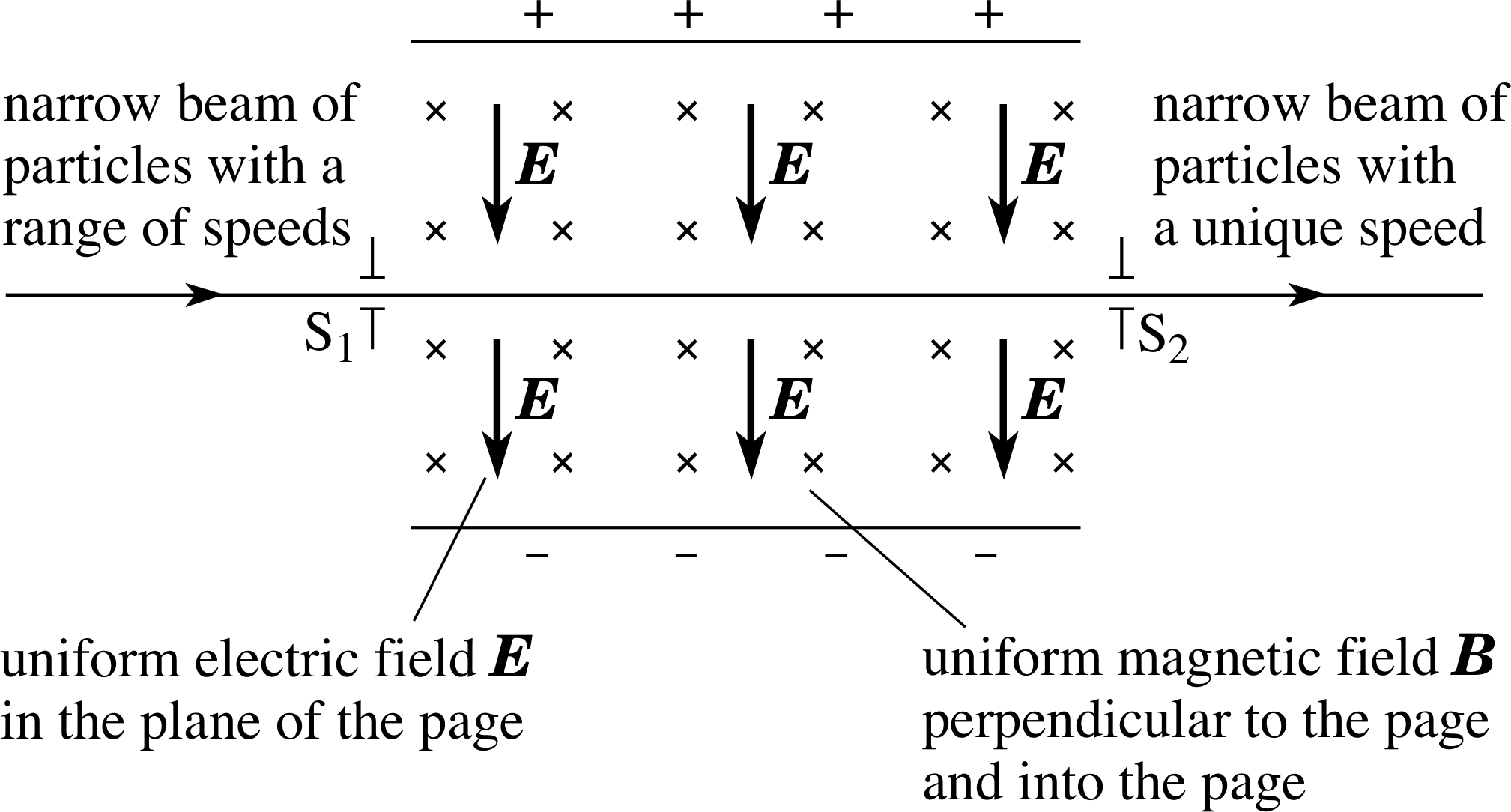
Figure 22 See Question E5.
Question E5 (A9)
Figure 22 shows a schematic diagram of a velocity selector. Explain why only those charged particles with a certain unique velocity will emerge through slit S2. If the electric and magnetic field strengths are 6000 V m−1 and 1.5 × 10⁻³ T, respectively, determine what will happen to positive ions that enter through S1 at speeds of 4.0 × 10⁶ m s−1 and 5.0 × 10⁶ m s−1.
Answer E5
The ions are positive so the electric force acts in the direction of E in Figure 22 and the initial
magnetic force acts opposite to this. For an ion to pass undeflected through the field region, the net Lorentz force must be zero, i.e. qE = qBυ (see Equation 31)
eBυ = eE(Eqn 31)
so only ions with the following speed will be undeflected:
υ = E/B = 6.0 × 10³ V m−1/1.5 × 10−3 T = 4.0 × 10⁶ m s−1
Therefore ions entering S1 at 4.0 × 10⁶ m s−1 will be undeviated. For ions travelling at 5.0 × 10⁶ m s−1, the magnitude qBυ will be greater than qE so the ions will be deflected towards the positive plate in Figure 22 and they will not reach S2.
(Reread Subsection 5.2 if you had difficulty with this question.)
Question E6 (A10)
A small rectangular metal sheet of thickness t has a current along its length l. A Hall voltage VHall is generated across its width d when the sheet is placed perpendicular to a uniform magnetic field. The number density of free electrons of charge −e in the sheet is n. Show that there is a magnetic force on the sheet whose magnitude is netlVHall.
Answer E6
The Hall voltage may be expressed as:
VHall = IB/net(Eqn 39)
The magnetic force on the sheet is given by Equation 1 (with θ = 90°):
Fmag = IlB sin θ 0 ≤ θ < 180°(Eqn 1)
so,Fmag = IlB = netlVHall
as required.
(Reread Subsection 5.5 if you had difficulty with this question.)
Study comment This is the final Exit test question. When you have completed the Exit test go back and try the Subsection 1.2Fast track questions if you have not already done so.
If you have completed both the Fast track questions and the Exit test, then you have finished the module and may leave it here.
Study comment Having seen the Fast track questions you may feel that it would be wiser to follow the normal route through the module and to proceed directly to the following Ready to study? Subsection.
Alternatively, you may still be sufficiently comfortable with the material covered by the module to proceed directly to the Section 6Closing items.