PHYS 2.7: Rotational mechanics |
PPLATO @ | |||||
PPLATO / FLAP (Flexible Learning Approach To Physics) |
||||||
|
1 Opening items
1.1 Module introduction
The turning action of a force has been well known for thousands of years, since the first time a human used a stick as a lever. The crowbar and the balance, which make use of this turning action, have been tools since the beginning of recorded history. The scientific study of their effects dates back to Archimedes (287–212 BC), who seems to have been the first to express the mathematical law of the lever, and Galileo Galilei (1564–1642) who, in the early seventeenth century, formulated a clear measure of the turning action or torque produced by a force. He popularized the expression moment of a force for this measure. Engineers and craftsmen involved in the design and operation of rotating machinery, such as watermills, grain crushers, and lathes, had known informally about the relations between torque, rotational acceleration and rotational inertia, but the first scientific and mathematical study of these relations was carried out by Daniel Bernoulli (1700–1782) and Leonhard Euler (1707–1783) in the early eighteenth century. The modern laws of rotational dynamics are mainly due to Euler.
Rotational motion can be extremely complicated, with the axis of rotation changing orientation and moving through space while the body, or parts of it, move around the axis (think of the contortions of a skilled high–board diver, for example). To keep the discussion as simple as possible, this module restricts attention to the special case of uni-axial rotation in which the axis maintains a fixed orientation. An opening door or a wheel rolling down a hill provide good examples of this type of motion. It is important to bear this restriction in mind because some of the statements made in this module cannot be extended to more general situations. The concept of angular momentum, which allows us to discuss what happens when the axis of rotation changes its orientation is introduced elsewhere in FLAP.
This module begins by considering the conditions needed for bodies to be static. Section 2 deals with the equilibrium of bodies under the action of balanced torques and examines what determines the magnitude of a torque and how it is measured and represented mathematically, in terms of scalars, using the concept of a moment of a force. Section 3 extends the discussion to the vector representation of torque and introduces two mathematical tools – unit vectors and vector or cross products. Section 4 introduces the kinematic equations of uniform angular acceleration around an axis of fixed orientation and draws an analogy with uniform acceleration along a straight line.
In Section 5 we apply Newton’s laws of motion to uni–axial rotational motion and show that when a torque acts on a body the resulting angular acceleration depends on the magnitude of the torque and also on the moment of inertia of the body, which measures its intrinsic reluctance to undergo angular acceleration. Moments of inertia are calculated for simple shapes. Section 5 also introduces rotational kinetic energy, and shows how to consider this either as rotation about an axis which is instantaneously at rest or as translational energy of the centre of mass together with rotational energy around the centre of mass. The parallel-axis theorem is used to establish the connection between these two approaches.
Study comment Having read the introduction you may feel that you are already familiar with the material covered by this module and that you do not need to study it. If so, try the following Fast track questions. If not, proceed directly to the Subsection 1.3Ready to study? Subsection.
1.2 Fast track questions
Study comment Can you answer the following Fast track questions? If you answer the questions successfully you need only glance through the module before looking at the Subsection 6.1Module summary and the Subsection 6.2Achievements. If you are sure that you can meet each of these achievements, try the Subsection 6.3Exit test. If you have difficulty with only one or two of the questions you should follow the guidance given in the answers and read the relevant parts of the module. However, if you have difficulty with more than two of the Exit questions you are strongly advised to study the whole module.
The acceleration due to gravity g, which varies with latitude and height, will be approximated to 10 m s−2, unless otherwise specified.
Question F1
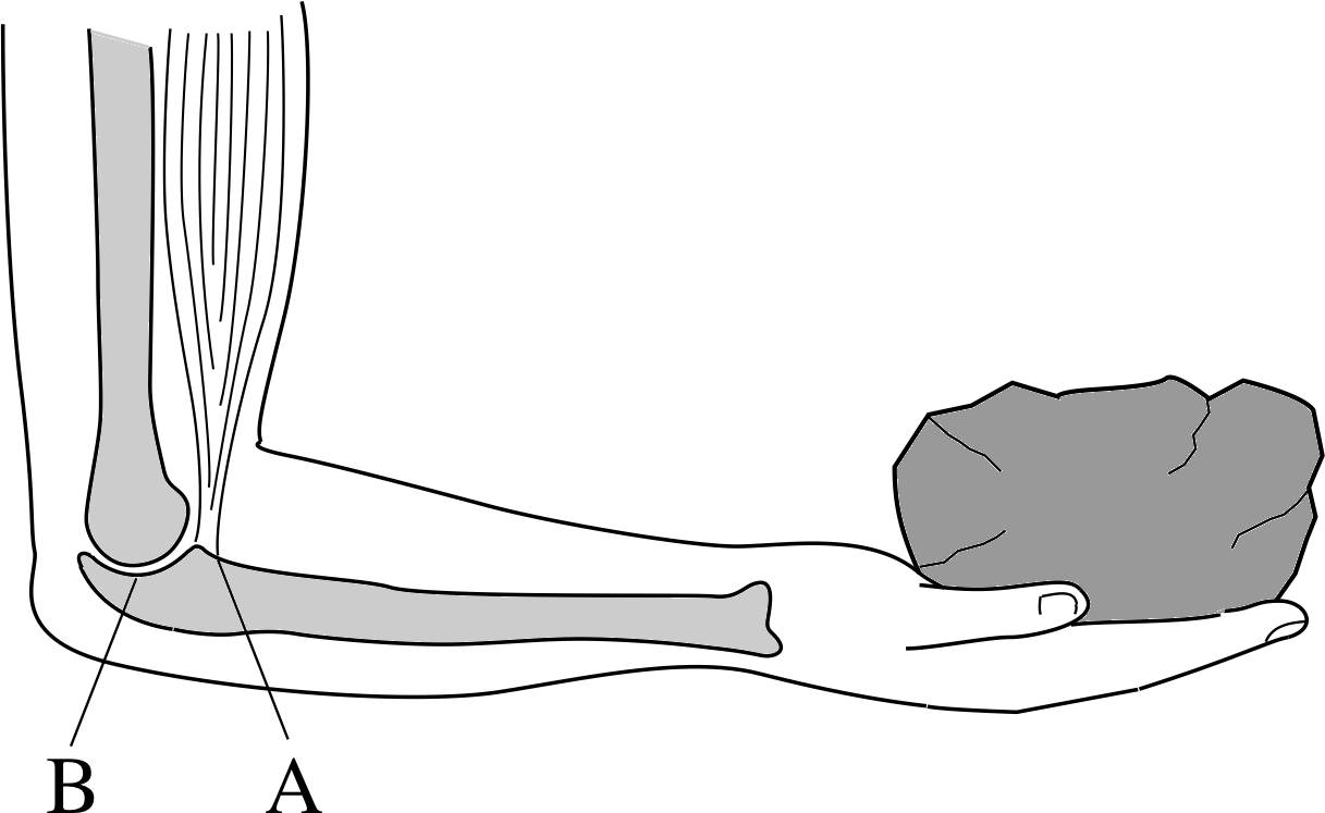
Figure 1 See Question F1.
Figure 1 shows a sketch of a forearm supporting the weight of an object. (Assume that A and B are on the same horizontal level.) Suppose the object has a mass of 2 kg in this case. The biceps muscle, which exerts an upwards force, is attached at point A, further forward than the elbow joint B. Take g = 10 m s−2.
- (a)
-
Identify the fulcrum in this case.
- (b)
-
Draw an idealized diagram representing the fulcrum, arm and all forces acting on the forearm. Explain qualitatively why there must be a force on the forearm at the elbow joint B.
- (c)
-
Write down the equations of translational and rotational equilibrium for the forearm using scalar notation.
- (d)
-
Now use your own forearm to estimate the distance between the attachment point of the biceps muscle A and the elbow joint B. Also estimate the weight of the forearm. Use these estimated values to find the magnitude of the tension in the biceps muscle and the force on the forearm at the elbow joint.
- (e)
-
Add x-, y-, z–axes to your diagram, with origin at the elbowjoint, and calculate the vector torque exerted by the weight of the 2 kg object using unit vectors, i, j, and k, and a vector cross product.
Answer F1
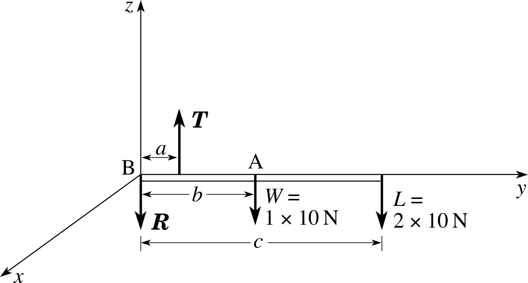
Figure 18 See Answer F1.
(a) The fulcrum in this case is the horizontal axis, perpendicular to the page, passing through the elbow joint at B.
(b) Figure 18 shows the forces on an idealized diagram. R is the reaction at the elbow joint, T is the tension in the biceps muscle, W is the weight of the arm and L is the weight of the object. Without the force R, it would be impossible to achieve rotational equilibrium. This is seen most easily by taking moments about the centre of mass of the arm. The forces T and L from the biceps muscle and the object both promote clockwise rotation. This can only be balanced if there is a downwards force R at the elbow joint. Since none of the other forces have horizontal components the force R must act vertically downwards in order to ensure translational equilibrium.
(c) For translational equilibrium:
T − R − W − L = 0
For rotational equilibrium, taking moments about the elbow (point B), and taking anticlockwise moments to be positive:
aT − bW − cL = 0
(d) Suppose a = 4 cm, b = 16 cm, c = 32 cm and the weight of the forearm W = 1 × 10 N, where the magnitude of the acceleration due to gravity is rounded up to 10 m s−2. We have L = mg = 2 × 10 N and the translational equilibrium condition becomes:
T − R = 30 N
The rotational equilibrium condition about B does not involve R and becomes:
T × (0.04 m) = 10 N × (0.16 m) + 20 N × (0.32 m) = 8.0 N m
i.e.T = 8.0 N m/(0.04 m) = 200 N
Substituting for T in the first equation then gives R = 170 N.
(e) Figure 18 shows a right–handed Cartesian coordinate system with origin at the elbow. The general expression for the torque Γ of a force F applied at position r is Γ = r × F. Here we need the torque from L about B. This is:
Γ = (0.32 m) j × (20 N)(− k) = −0.32 × 2 (j × k) N m = −6.4 i N m
This torque vector points along the negative x–axis. This tells us that someone on the positive side of the x–axis, looking towards the origin, will see an associated clockwise sense of rotation associated with this, as expected.
Question F2
A concrete column of uniform circular section and density 2.4 × 10³ kg m−3 is 40 m long and has a diameter of 1.5 m. The column is rolling (without slipping) down a slope which is at 10° to the horizontal.
(a) Calculate the moment of inertia of the column about a central axis parallel to its length.
(b) Calculate the moment of inertia of the column about its line of contact with the sloping surface.
(c) Calculate the resultant torque vector acting on the column about the axis in (b).
(d) Find the angular acceleration vector of the column about this axis.
(e) What will be the angular velocity vector of the column about this axis 2.0 s after being released from rest?
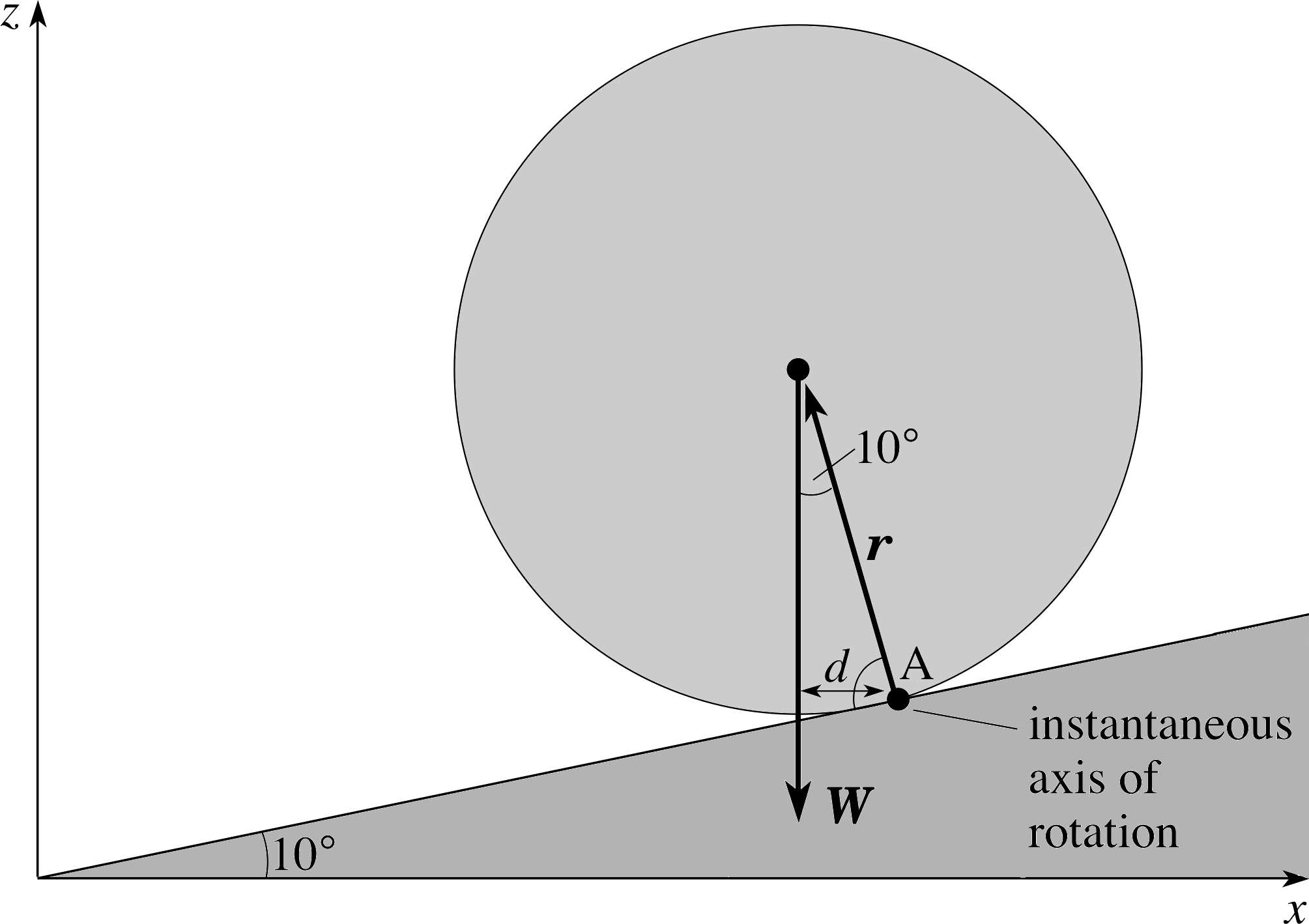
Figure 19 See Answer F2.
Answer F2
(a) The moment of inertia of the column about the central axis is
I = Mr2/2 = πr2lρr2/2 = πr4lρ/2 = π (0.75 m)4 × 40 m × 2.4 × 103 kg m−3/2 = 4.8 × 10⁴ kg m2.
(b) Using the parallel–axis theorem
I = Mr2/2 + Mr2 = 3Mr2/2 = 1.4 × 10⁵ kg m2
(c) Figure 19 shows a side elevation of the rolling column.
The torque Γ about the line of contact through A, due to the weight W, is
Γ = r × W
which has a direction out of the plane of Figure 19 (towards you)
and a magnitude
Γ = r W sin 170° = r × πr2lρg2 sin 170° = πr3lρg sin 170°
Γ = π (0.75 m)3 × 40 m × 2.4 × 103 kg m−3 × 10 m s−2 × 0.174 = 2.2 × 10⁵ N m
(d) From the basic law of rotational dynamics for uni–axial motion Γ = Iα. The magnitude of the angular acceleration is α = Γ/I = 2.2 × 10⁵ N m/1.4 × 105 kg m2 = 1.6 rad s−2. The direction of the angular acceleration vector is along Γ (i.e. out of the page, towards you).
(e) Since the angular acceleration is constant and the initial angular velocity is 0, the final angular velocity is ω = α t. Thus the magnitude of the angular velocity vector is
ω = 1.6 rad s−2 × 2 s = 3.2 rad s−1 and its direction is along α (out of the page, towards you).
1.3 Ready to study?
Study comment In order to study this module you will need to understand the following terms: angleangular measure (degree, radian, the relationship s = rθ between arc length s, radius r and angle swept out θ), areaareas and volumevolumes of regular solids, Cartesian coordinate system, density, force, kinetic energy, mass, Newton’s laws of motion, SI units (distance, force and energy), translational equilibrium, uniform acceleration equations, uniform circular motion (angular speed, speed and the relationship between these), vectorvector notation (magnitude_of_a_vector_or_vector_quantitymagnitude, scalar component, component vector, vector addition, vector_differencevector subtraction), work, weight, algebraic_expressionalgebraic and trigonometric_functionstrigonometrical equations and manipulation of these. Note that although the derivativederivative notation dx/dt is widely used in this module to represent the rate of change of x with respect to t, you are not expected to be familiar with the techniques of differentiation. If you are uncertain about any of these terms then you can review them now by referring to the Glossary, which will indicate where in FLAP they are introduced. The following questions will allow you to establish whether you need to review some of the topics before embarking on the module.
Question R1
When a mountain on the equator rotates through 2° because of the revolution of the Earth, through what distance has it moved? Calculate its angular speed and speed. The radius of the Earth is 6.38 × 10⁶ m.
Answer R1
Since the arcarc of a circle = radius × angle in radians, the distance moved by the mountain is
rθ = (6.38 × 10⁶m) × 2 × π/180 = 2.23 × 10⁵m.
If the angular speed is ω and the period of the Earth’s rotation is T = 24 hr, then
ω = 2π/T = 2π/(24 × 60 × 60) s = 7.27 × 10⁻⁵ rad s−1
and the speed is υ = rω = 6.38 × 106 m × 7.27 × 10−5 rad s−1 = 464 m s−1
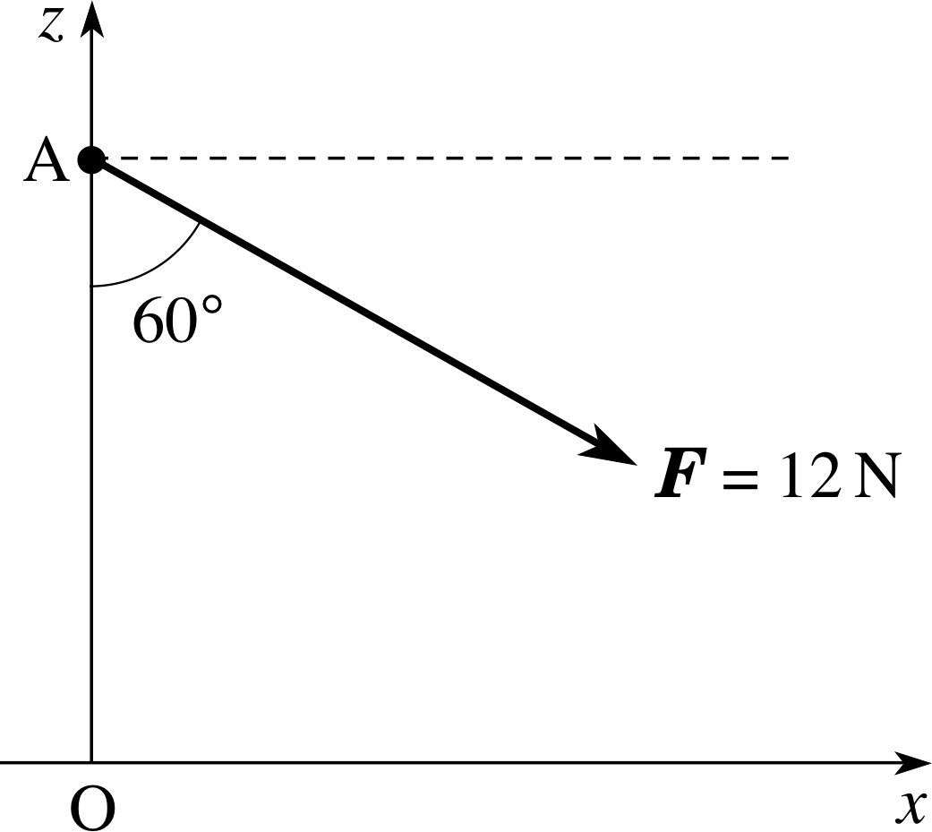
Figure 2 See Question R2.
Question R2
Find the components_of_a_vectorcomponents of the force F of magnitude 12 N along both the x– and z–axes in Figure 2. If this force F were applied to an object of mass 3.0 kg, placed at A, write down the components of the resulting acceleration of the object.
Answer R2
The components_of_a_vectorcomponent of a force along a given direction is given by the product of the magnitude_of_a_vector_or_vector_quantitymagnitude of the force and the cosine of the angle between the force and the direction concerned. From Figure 2, the force is at an angle of 30° to the positive x–direction and 60° to the negative z–direction.
The x–component of F is
Fx = F cos 30° = (12 N) cos 30° = 10.4 N
The z–component of F is
Fz = −(12 N) cos 60° = −6.0 N
Newton’s second law of motion is F = ma, which leads to
ax = Fx/m = 10.4 N/3.0 kg = 3.5 m s−2 and az = Fz/m = −6.0 N/3.0 kg = −2.0 m s−2
Question R3
A mains water pipe section is of length 24 m, outer diameter 0.80 m, inner diameter 0.74 m and density 2.4 × 10³ kg m−3. Calculate its mass and its weight (taking the magnitude of the acceleration due to gravity to be 10 m s−2).
Answer R3
We solve this problem by subtracting a smaller from a larger imaginary solid pipe, having the given inner and outer radii, respectively.
Since mass = density × volume, it is necessary first to calculate the volumes of these solids. Do not forget to divide the diameter by 2 in order to calculate the radius.
The volume of a cylindrical solid = cross–sectional area × height = πr2h.
The volume of the larger pipe is, therefore, π (0.40 m)2 × 24 m.
The volume of the smaller pipe is π (0.37 m)2 × 24 m.
The mass of the hollow pipe is, therefore,
density × volume = 2.4 × 10³ kg m−3 (0.42 − 0.372) m2 × 24 m × π = 4.2 × 10³ kg
The weight of the pipe acts downwards and has magnitude
mg = 4.2 × 103 kg × 10 m s−2 = 4.2 × 10⁴ N
2 Torque
2.1 Introduction to torque
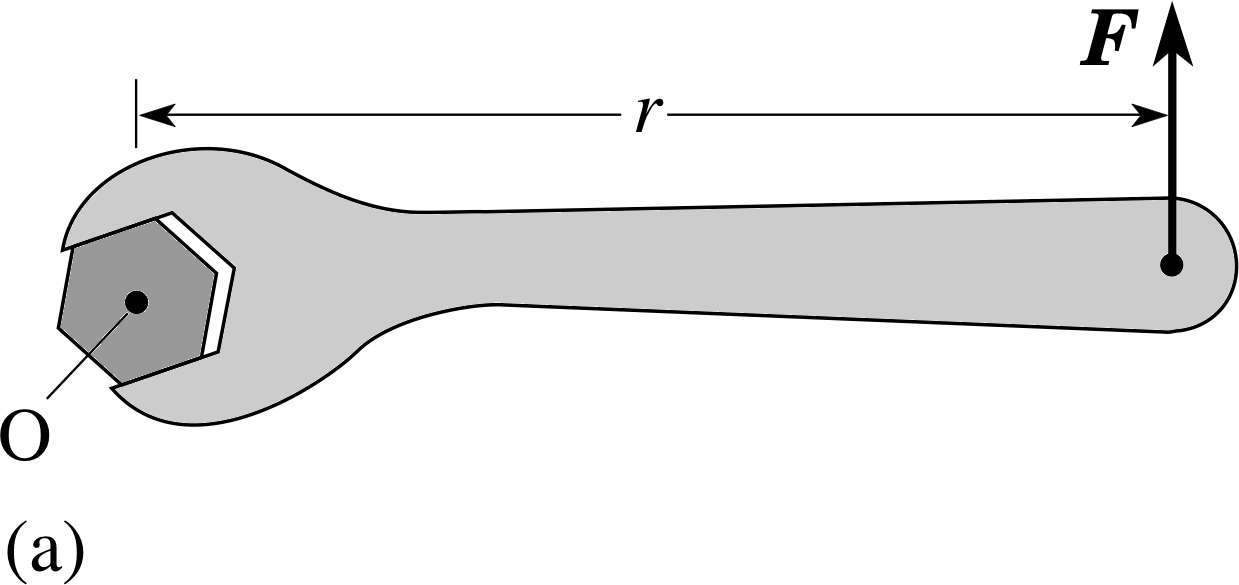
Figure 3a Increasing the torque. If the frictional torque between nut and bolt balances the applied torque.
When we turn a tap on or off, or use a spanner or a screwdriver, we are applying a torque to a body. i Torque is a measure of the turning effect of a force on a body. A torque is also sometimes referred to as the moment of a force, which we will discuss in Subsection 2.3.
Figure 3a shows a torque applied with a spanner to loosen a nut, using a force at right angles to the shaft of the spanner. The fulcrum of a torque is the line around which the turning can be regarded as taking place, sometimes called the axis of rotation.
In Figure 3a the fulcrum is naturally taken to be a line perpendicular to the page that passes through the point O at the centre of the nut.
Suppose that the nut in Figure 3a is too tight and will not turn?
The fact that the nut won’t turn implies that there is equilibrium between the applied torque and some other torque, and this other torque can only be due to friction between nut and bolt. We might try to push harder by, say, doubling the applied force to 2F (Figure 3b). Alternatively, we could use the same force but apply it at, say, twice the distance from the fulcrum, 2r, with the help of an extension pipe (Figure 3c).
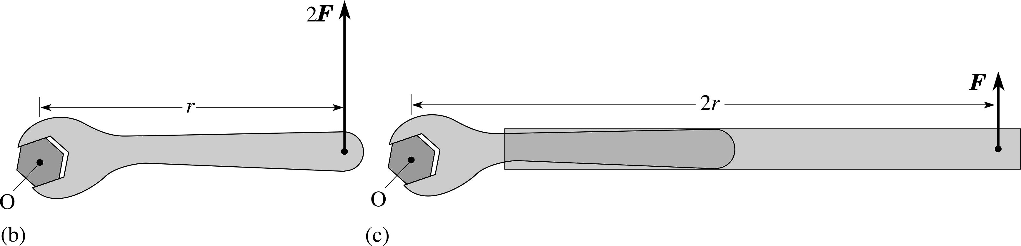
Figure 3 Increasing the torque. The torque may be increased by increasing the force as in (b), or increasing the distance to the fulcrum as in (c).
Both methods increase the torque on the nut, but it could be that the nut still doesn’t turn! We might need both strategies, with the doubled force at double the distance from the fulcrum. In a situation like this, where the applied force acts at right angles to the line joining the fulcrum to the point at which the force acts, the magnitude Γ of the torque is given by Γ = r F, where F is the magnitude of the force and r is the distance from the fulcrum to the point at which the force is applied. Thus doubling the force, or doubling the distance from the fulcrum, both double the torque, while performing both together quadruples the torque.
Question T1
Make a rough estimate of the maximum frictional torque if, to loosen a car wheel nut, it requires your whole weight, applied at the end of a horizontal spanner of length 0.40 m.
Answer T1
Suppose your weight is 700 N and that this is just sufficient to loosen the nut when you stand on a spanner of length 0.4 m, fitted horizontally. The size of the torque due to your weight is:
Γ = 700 N × 0.40 m = 280 N m.
This must also be the maximum frictional torque on the nut.
Question T2
In Question T1, not only the nut feels the torque. The torque is experienced also by the whole wheel. What prevents the wheel from slipping in such circumstances?
Answer T2
The friction of the ground acting on the tyre prevents the wheel from slipping. As you begin to jack up the wheel the maximum friction available reduces and the wheel is more likely to slip – this is why the wheel nuts should be loosened slightly before the wheel and tyre are lifted off the ground.
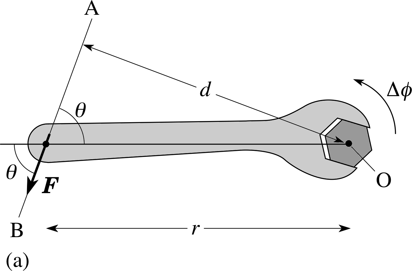
Figure 4 (a) Construction lines for calculating torque magnitudes. AB represents the line of action of a force F and d is the perpendicular distance between the fulcrum and AB.
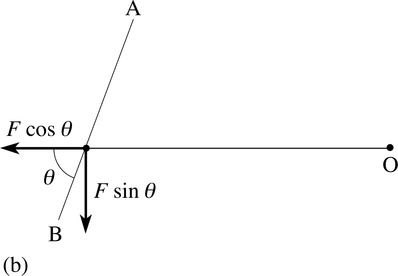
Figure 4 (b) The decomposition of the applied force into two component vectors whose lines of action are (i) through the fulcrum and (ii) perpendicular to this direction.
Now suppose the force is applied not at right angles to the spanner shaft, but at an angle θ to it, as in Figure 4a. Then the magnitude of the torque will be less than before.
The construction line AB in Figure 4a, which extends (in both directions) the vector arrow representing the force, is called the line of action of the force. If we were foolish enough to apply the force with its line of action along the shaft of the spanner then the torque would be zero and the nut would never rotate, no matter how large a force were applied: forces whose line of action passes through the fulcrum produce no torque.
We can summarize these conclusions by stating that the torque produced by a force depends on three factors:
- the magnitude of the force;
- the distance of the point of application of the force from the fulcrum;
- the direction of the force.
We can make these observations more quantitative if we resolve the force F acting in Figure 4a into component vectors perpendicular to the shaft and along the shaft, as shown in Figure 4b. The force component vector along the shaft has magnitude F cos θ and that perpendicular to the shaft has magnitude F sin θ, where θ is the angle between the shaft and the original force direction. The force component vector along the shaft produces no torque since its line of action passes through the fulcrum. The force component vector perpendicular to the shaft produces a torque of magnitude Γ = r F sin θ. This is the magnitude of the total torque produced by F about the fulcrum through O.
This result can also be interpreted in a more geometric way. Noting that the perpendicular distance between the fulcrum and the line AB is d = r sin θ, we can write:
torque magnitude Γ = r F sin θ = Fd(1)
where d is the perpendicular distance between the fulcrum and the line of action of the force. This simple example of a spanner and a nut illustrates quite a lot of physics!
- 1
-
Although torques are caused by forces they are different from forces. It is possible to change the magnitude of the torque without changing the magnitude of the force – simply by changing the direction of the force or its distance from the fulcrum.
- 2
-
The magnitude of the torque is the product of the magnitude of the force and the perpendicular distance between its line of action and the fulcrum – so the units of torque are those of force × distance, or N m. You may recall other quantities in physics which have units of force × distance. For example, the work done by a force acting through a distance and the kinetic energy gained by a body subject to such work both have units of force × distance. In the case of work or kinetic energy, this unit is called the joule (1 J = 1 N m). We must be very careful not to confuse the torque from a force with the work done by a force. These clearly measure totally different quantities – the turning effect and the energy transferred. Torque should be expressed in N m but never in J.
- 3
-
When a torque is applied to a body it does not always produce rotation of the body. The frictional forces between the surfaces of the threads on the nut and bolt can exert opposing torques about the same fulcrum and only when the torque from the spanner exceeds the maximum frictional torque does the rotation begin. This is analogous to attempting to slide a body on a rough surface where, in order to start the motion, we need to apply a force that exceeds the maximum frictional force. It requires an unbalanced torque to cause an initially non–rotating body to start to rotate, just as it requires an unbalanced force on an initially stationary body to start it to move.
Question T3
An aerial mast 5 m high is secured by a set of tie cords which are attached to the mast 1 m from the top. If each cord is secured to the ground 8 m from the mast and stretched to a tension of 120 N, find the magnitude of the torque exerted by a single cord about a fulcrum at the base of the mast.
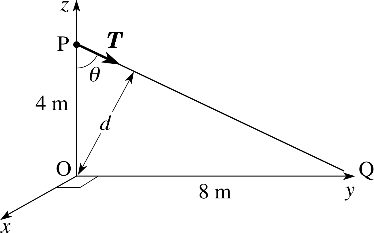
Figure 20 See Answer T3.
Answer T3
Figure 20 shows the tension force, T, and one of the tie cords, PQ, in side elevation. Using Equation 1,
torque magnitude Γ = r F sin θ = Fd(Eqn 1)
the magnitude of the torque about O is:
Γ = Td = r T sin θ = 120 N × 4 m × [8 m/(42 + 82)1/2 m] = 429 N m
Question T4
For the aerial mast of Question T3, calculate the magnitude of the torque exerted by a single cord about a fulcrum which is: (a) parallel to the ground and intersects the mast 1 m above the ground, and (b) parallel to the ground and intersects the mast at the point of attachment of the cord.
Answer T4
We can refer again to Figure 20. (a) If the fulcrum is taken to be on the mast 1 m above the ground, then it is 3 m below the point of attachment of the cord at P. The torque about this fulcrum is calculated as in Answer T3, but with 3 m replacing the 4 m in that calculation (θ is the same):
Γ ′ = T d ′ = r ′ T sin θ = 120 N × 3 m × [8 m/(42 + 82)1/2 m] = 322 N m
(b) If the fulcrum is taken to be coincident with the point of attachment of the cord at P then the distance of the line of action of the force from the fulcrum is zero and so the torque is zero.
We again stress the difference between forces and torques. A force may be fully specified by giving its vector (i.e. its magnitude and direction), but a torque is specified by giving the force vector and its line of action in relation to some specified fulcrum. If the fulcrum is changed then the torque from a given force will change; it is meaningless to speak of torque without also specifying the fulcrum. In particular:
There is no torque about a fulcrum that lies on the line of action of the force.
2.2 Work and power
Figure 4 (b) The decomposition of the applied force into two component vectors whose lines of action are (i) through the fulcrum and (ii) perpendicular to this direction.
If we succeed in turning the nut of Subsection 2.1, we will do a certain amount of work. This work is directly related to the torque that is applied and to the angle through which the nut is turned. We now calculate the work done by the force F in turning the nut through a small angle ∆ϕ. We consider the general case in which the force is not necessarily at right angles to the line from the fulcrum to the point of application of the force (Figure 4).
When the spanner rotates through a very small angle ∆ϕ the distance moved by the point of application of the force is ∆x = r | ∆ϕ | i and the component of force in the direction of the displacement is F sin θ.
Since the work done by a force is given by the product of the distance moved and the force component in the direction of the displacement, we can state the following general result.
The work done by a torque of magnitude Γ in turning through a small angle ∆ϕ is given by:
∆W = F sin θ ∆x = F sin θ r | ∆ϕ | = Γ | ∆ϕ |(2a) i
where the angle ∆ϕ must be measured in radians. Because both work and angle are additive quantities, the total work done when a torque of constant magnitude Γ rotates the spanner through any angle ϕ is given by
W = Γ | ϕ |(2b)
If the small rotation ∆ϕ is completed in a time ∆t we can also derive an expression for the power supplied.
The power supplied by a torque Γ in turning through an angle ∆ϕ in a time ∆t is
$P = \dfrac{\Delta W}{\Delta t} = \it{\Gamma}\,\left\lvert\,\dfrac{\Delta \phi}{\Delta t}\,\right\rvert = \it{\Gamma}\omega$(3)
where the angular speed $\omega = \left\vert\,\dfrac{\Delta\phi}{\Delta t}\,\right\rvert$ must be measured in radian s−1. i
Of course, these results do not just apply to spanners and nuts! They apply to the rotation of any object which can be regarded as being rigid. (A rigid body is one that cannot be squashed or stretched, so there is no need to worry about the possible conversion of energy into forms associated with elastic deformation.)
Question T5
Suppose that in the situation described in Question T1 it is found that once the nut begins to move, the average torque over one revolution is 1/4 of its initial value. Calculate the work done in one revolution of the spanner and the average power needed to complete this operation in a time of 5 s.
[For reference: Question T1. Make a rough estimate of the maximum frictional torque if, to loosen a car wheel nut, it requires your whole weight, applied at the end of a horizontal spanner of length 0.40 m.]
Answer T5
Equation 2b,
W = Γ | ϕ |(Eqn 2b)
gives the work done as the average torque multiplied by the angle (in radians). The angle turned through is one revolution (2π radians) and the average torque Γ = 280 N m/4 = 70.0 N m. So, ∆W = 70 N m × 2π = 440 J. If this is completed in 5 s, the average power is given by Equation 3,
$P=\dfrac{\Delta W}{\Delta t} = \it{\Gamma}\,\left\lvert\,\dfrac{\Delta \phi}{\Delta t}\,\right\rvert = \it{\Gamma}\omega$(Eqn 3)
asP = ∆W/∆t = 440 J/5 s = 88.0 W.
2.3 The centre of mass
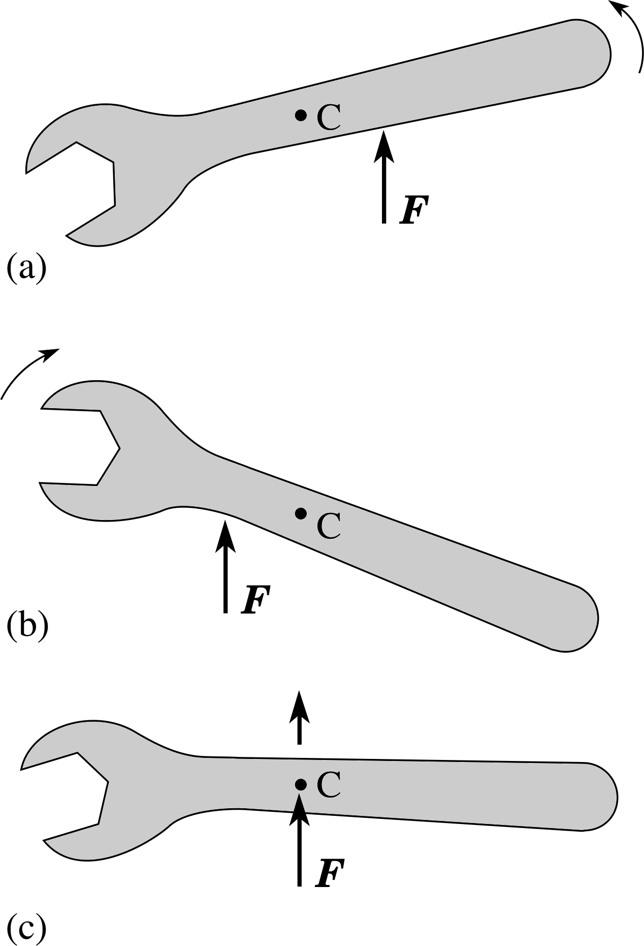
Figure 5 Plan view of a spanner placed on a horizontal surface of very low friction. If the line of action of the horizontal force F is to the right of the centre of mass C the body will rotate anticlockwise and will translate. If it acts to the left of C, then translation and clockwise rotation will occur. If it passes through C then the spanner will translate but not rotate.
The wheel nut is an example of a body subject to several forces, including those from the spanner and from the bolt thread. If we apply a single force to a free body, then we cannot produce a rotation alone, since Newton’s second law tells us that the unbalanced force must produce an acceleration of the body as a whole.
Although we cannot arrange for the single force to produce rotation without translational acceleration, it is possible for a single force to produce translational acceleration without causing any rotation, provided the line of action of the force passes through a special point for the body, called its centre of mass. Figure 5 shows this effect.
The centre of mass of a rigid body is defined as the special point with the property that any force whose line of action passes through the centre of mass produces translation but no rotation of the body. The centre of mass is unique: each body has just one.
Just as mass is a fundamental property of any object, so too is the centre of mass. Precisely because the centre of mass is unique, its location can often be anticipated in a symmetric body. For example, in a homogeneous sphere, cube or rectangular cuboid the centre of mass is at the centre of the object – it could hardly be anywhere else. For other bodies the centre of mass can be found experimentally or mathematically.
The centre of mass can also be defined for non–rigid bodies or even for a collection of particles or objects that are not connected together. If the objects are imagined as being joined together for an instant (∆t = 0) by massless rigid rods then the centre of mass of this imaginary system is at the same point as the centre of mass of the collection of objects.
It is worth noting that the centre of mass has a second important property which is not connected with rotation. The centre of mass of an extended object, moves through space just like a particle that experiences the total external force acting on the body. In other words, the centre of mass is guaranteed to behave just like the mythical point–particle of Newtonian mechanics. For example, the centre of mass of a somersaulting gymnast (somewhere near her navel) follows a parabolic path, although the same need not be true for other parts of her body, such as her head or feet. This makes it convenient to describe the motion of an extended body in terms of the motion of its centre of mass, together with any rotation that takes place about an axis through the centre of mass. In fact Euler proved that such a description can always be given: the instantaneous motion of any rigid body can always be described as a translation of its centre of mass, accompanied by a rotation about an axis through the centre of mass.
In general, the centre of mass of a body should not be confused with its centre of gravity. For the purposes of calculating the gravitational force on an extended body it is possible to imagine the real body as being replaced by a point mass, equal to the mass of the whole body, and placed at a special point, called the centre of gravity of the body. This is the point at which the whole mass of the body can be considered to reside, as far as the gravitational forces acting on it are concerned. If gravity is uniform, i.e. if the body is small, the centre of gravity and the centre of mass coincide. In such a case, gravity exerts no torque about a fulcrum passing through the centre of mass. This means that, although gravity causes an initially stationary rigid body to accelerate downwards, it cannot cause it to rotate. More generally, though, gravity may vary from one part of the body to another. In this case, the centre of gravity does not coincide with the centre of mass, and gravity can cause both acceleration of the centre of mass and rotation around it.
Near the Earth’s surface, gravity is uniform so the centre of gravity does coincide with the centre of mass. This forms the basis of an experimental method for determining the centre of mass of any rigid body by suspending it from a single thread. Since the weight of the body acts, effectively, at the centre of mass, it produces no torque about the centre of mass. When the body is static, the tension provided by the thread must also produce no torque about the centre of mass and this means that its line of action must pass through the centre of mass. Thus, the centre of mass can be located by suspending the body with the thread attached, in turn, to different points on the body and then finding the common intersection point of the lines of action of all the various thread tensions.
We have seen that it is possible for a single force to accelerate the centre of mass of a body without producing rotation, but that is not possible for a single force to produce rotation without accelerating the centre of mass. However, it is possible for two or more forces to do this. This is achieved by arranging for the forces to act such that their resultant force is zero but their resultant torque is not zero.
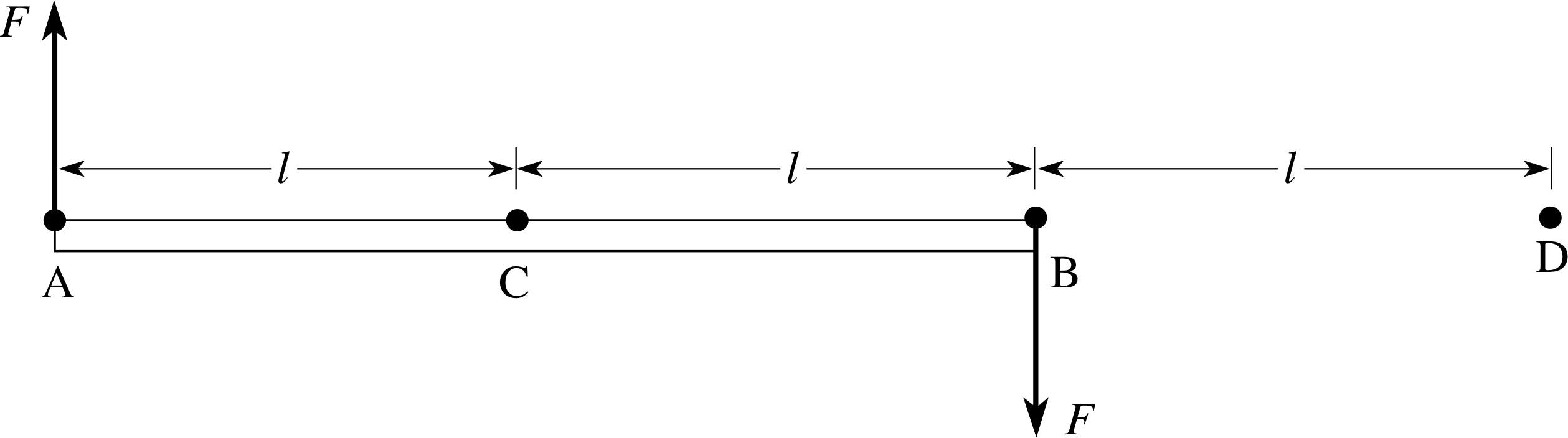
Figure 6 A rod (which is free to move) is acted upon by a couple.
The simplest case arises for two forces which have the same magnitude but point in opposite directions, as in Figure 6. Clearly, these forces have zero resultant, so they do not accelerate the centre of mass C. However, their torques reinforce one another (they both cause a clockwise rotation as we view the figure) so the resultant torque is not zero, and this causes the body to start to rotate. In general, such a pair of ‘equal and opposite’ forces, with a non–zero torque, is said to constitute a couple. For example, driving instructors recommend that a car be steered by applying a couple to the steering wheel. Note that the concept of a couple is quite different (and more restricted) than that of a torque.
When several torques act together on a body, the question of adding their effects arises. Sometimes, the torques reinforce one another, as in the case of a couple, and sometimes they cancel out. Two important questions arise immediately. First, how should we add the individual torques to find the resultant torque? Secondly, how does the body respond quantitatively to the resultant torque? We will deal with the first question in Subsection 2.4 and in Section 3. The second question will be tackled in Sections 4 and 5.
2.4 Combining torques – a scalar approach
There is a convenient and simple method to deal with the problem of combining torques for the case where all the vector forces act in a single plane (i.e. they are coplanar). In this case, we define the moment of a force to be the magnitude of the torque due to the force (as given by Equation 1), together with a sign which represents the sense in which the torque tends to promote rotation about the fulcrum. The resultant moment is then given by the algebraic sum of the moments of the separate forces (i.e. by adding the separate torques as signed scalar quantities). In these additions it is a common convention to take moments associated with anticlockwise rotations as being positive and those associated with clockwise rotations as negative, but there is no fundamental significance in this convention – the signs simply help us to see whether the different torques reinforce one another or not. At the end of the calculation, the magnitude of the resultant moment is equal to the magnitude of the resultant torque and the sign of the resultant moment tells us whether the promoted rotation is clockwise or anticlockwise. i
✦ From Figure 6 calculate the magnitude of the total torque (or moment) about a horizontal axis perpendicular to the rod and passing through (i) point A, (ii) point B, (iii) point C, and (iv) point D
(Ignore the weight of the rod.)
✧ (i) Taking anticlockwise moments to be positive, the moment about the axis through A is 0 − 2lF, which has magnitude 2lF.
(ii) The same answer is obtained when the axis passes through B.
(iii) When the axis passes through C each force has a perpendicular distance from the fulcrum of l, giving a resultant moment −lF −lF = −2lF, which again has magnitude 2lF.
(iv) About the fulcrum through D one force has a perpendicular distance of l, giving a moment lF, and the other force has a perpendicular distance of 3l giving a moment −3lF. The resultant moment about this fulcrum is therefore −2lF, which again has magnitude 2lF.
(Couples are unusual in that the magnitude of their resultant moment is independent of the choice of fulcrum. This is not true for arbitrary moments.)
2.5 Translational and rotational equilibrium
When a body is acted on by a set of forces whose resultant force is zero we say that the forces are balanced. According to Newton’s second law this situation corresponds to translational equilibrium – a state in which there is no acceleration, and the body moves at constant velocity or remains permanently at rest. An acceleration results when unbalanced forces act.
In the previous subsection we met the case of a body which was acted on by a couple. Since a couple produces a torque but no resultant force, the body must remain in translational equilibrium, even though the body rotates faster and faster, under the action of the torque. It is apparent that we need to extend our notion of equilibrium to include rotational equilibrium: full equilibrium implies both translational equilibrium and rotational equilibrium.
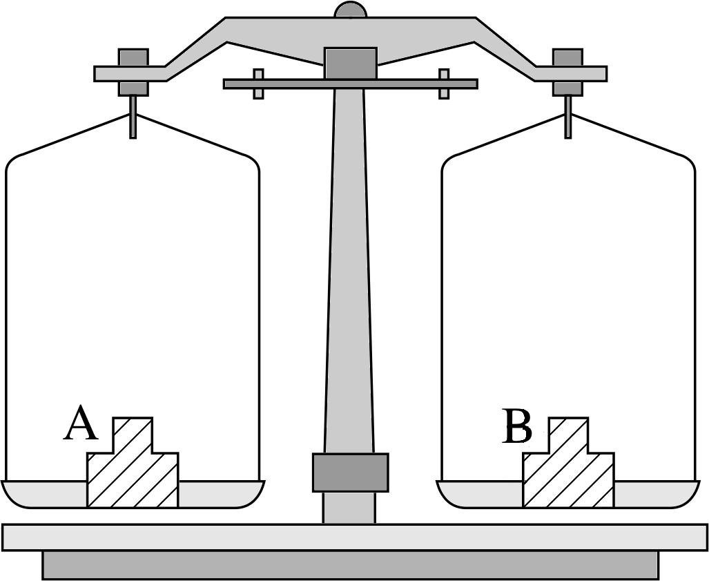
Figure 7a Rotational equilibrium with two weighing instruments. In the beam balance the moment of the weight on pan A about the pivot must balance the moment of the weight on pan B about the pivot.
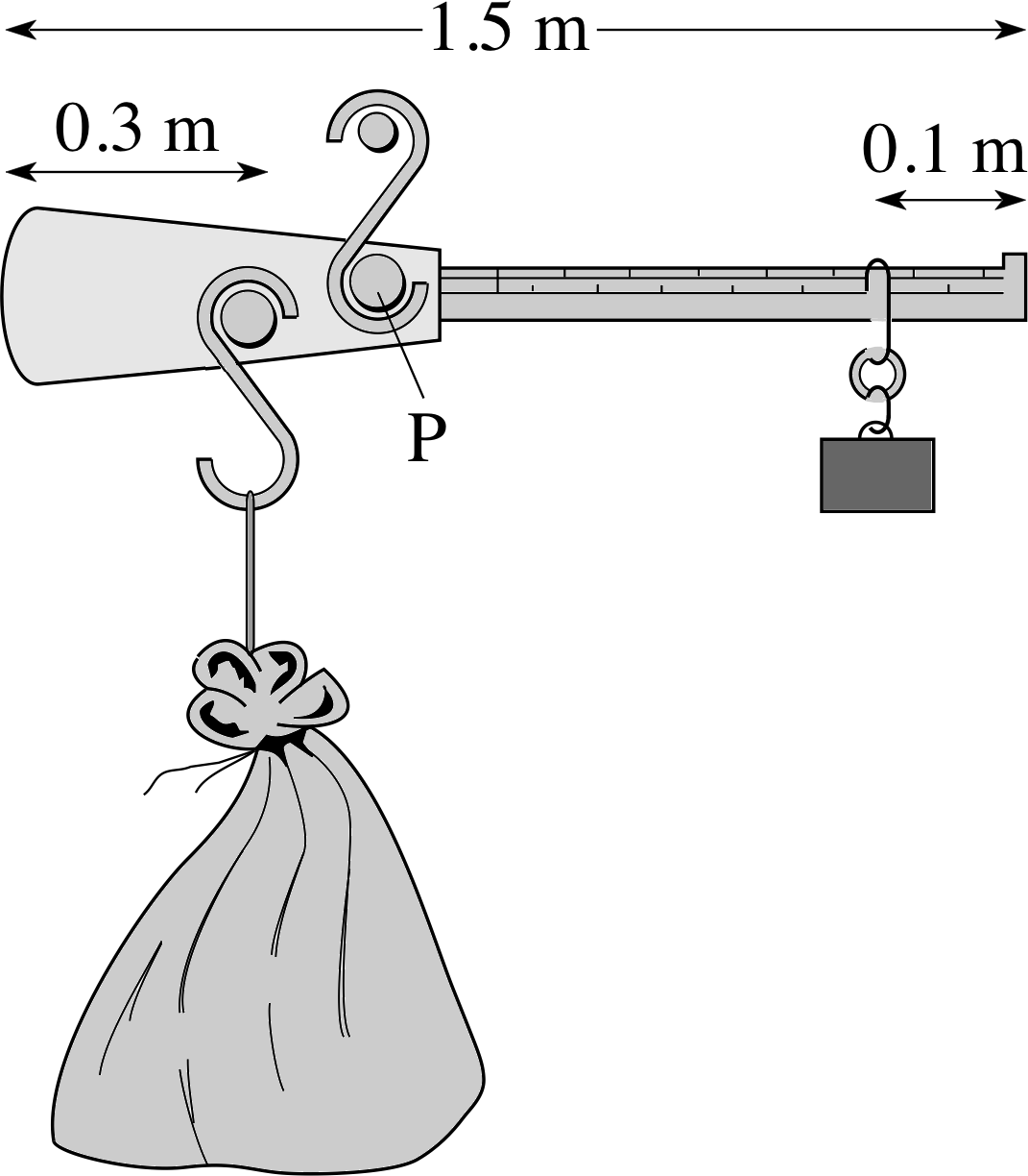
Figure 7b Rotational equilibrium with two weighing instruments. In the steelyard balance the moment of the larger weight must balance that of the smaller weight (the rider).
It is first necessary to agree on the distinction between translation and rotation. This is not entirely trivial. For example, when a door opens it is tempting to describe this as a pure rotation about a vertical axis through the hinges, but it is equally possible to describe the same motion as a translation of the centre of mass of the door (into the room), accompanied by a rotation of the door about a vertical axis through the centre of mass. Following Euler, we will generally use the latter description, keeping track of the translational motion of the centre of mass and then specifying the rotational motion about an axis through the centre of mass.
This leads to the following definitions:
- A body is said to be in translational equilibrium if its centre of mass remains at rest or moves with constant velocity. This condition implies that no unbalanced force acts on the body (the resultant force on the body is zero).
- A body is said to be in rotational equilibrium if it does not rotate or if it rotates at a constant rate about an axis of fixed orientation that passes through the centre of mass. This condition requires that no unbalanced torque acts on the body (the resultant torque on the body is zero).
- A body is in mechanical equilibrium if it is in translational equilibrium and rotational equilibrium. In mechanical equilibrium, there is no change in the state of motion of the centre of mass and no change in the state of rotation about the centre of mass. Mechanical equilibrium requires there to be no unbalanced force or torque acting on the body (the resultant force and resultant torque are both zero).
For coplanar forces, rotational equilibrium occurs when the resultant moment of all forces about the fulcrum is zero. This is known as the law of static moments. For example, in the beam balance in Figure 7a the moments of the two weights on the two scale pans must be of equal magnitude but of opposite sign for rotational equilibrium to be established. Since the two pans are at equal distances from the pivot as fulcrum and the two weights act at equal angles of 90° to the beam, the weights themselves must be equal.
For the steelyard balance, in Figure 7b, equilibrium is achieved by moving the fixed weight rider, so that its torque is varied until a balance is reached. Here the rider is much further from the fulcrum than is the load, so the balance is achieved when their distances from the fulcrum are in inverse proportion to their two weights.
Question T6
In the steelyard balance in Figure 7b the balance arm is 1.5 m long and is suspended from its centre of mass. If a mass of 20 kg, placed 30 cm from one end, is balanced by a mass of 3 kg placed 10 cm from the other end, find the position of the point of support P, which is also where the fulcrum intersects the balance arm.
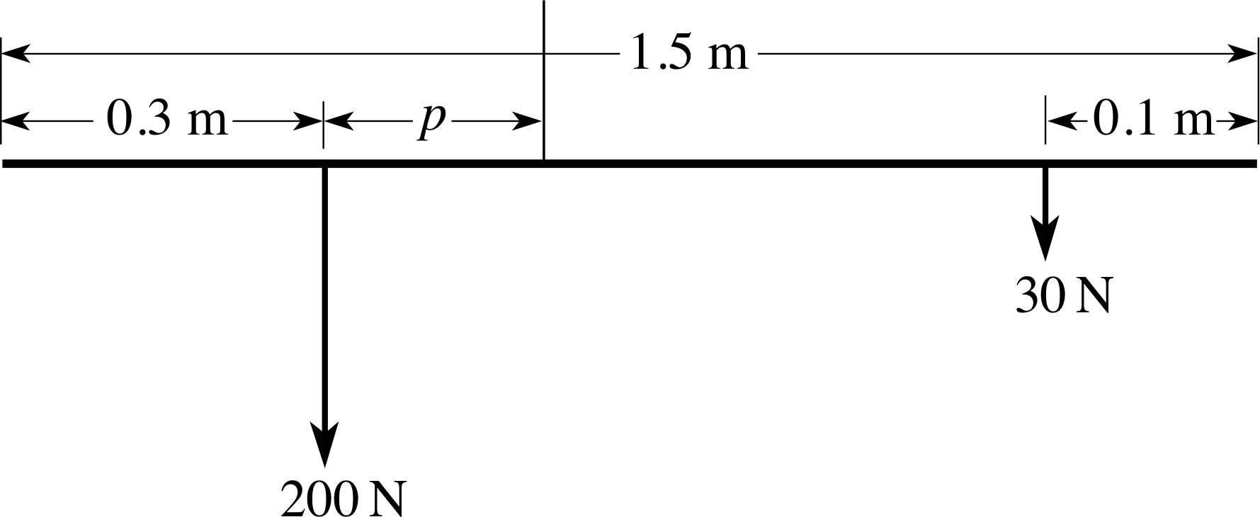
Figure 21 See Answer T6.
Answer T6
Figure 21 shows an idealized version of the balance. Suppose the point of support is at a distance p (in metres) from the line of action of the larger weight. The 20 kg mass has a weight of 20 kg × 10 m s−2 = 200 N. Similarly the weight of the 3 kg mass is 30 N. The magnitude of the moment of the 200 N weight about the point of support is (200p) N m and since this moment promotes an anticlockwise rotation we take it to be positive. The magnitude of the moment of the 30 N weight is
30 N × [1.5 − (0.3 + p) − 0.1] m = 30 × (1.1 − p) N m
Since this moment promotes a clockwise rotation we take it to be negative.
Rotational equilibrium requires that the resultant moment be zero so
(200p) N m − [30 × (1.1 − p)] N m = 0.
Hence p = 33 N m/(230 N) = 0.14 m.
Hence the point of support is 0.14 m from the line of action of the larger weight.
3 Torques using vector notation
The approach used in Subsection 2.5 represented the torques as moments of forces, which were signed scalar quantities. This is fine for coplanar forces, where rotations involve a single axis, but it is not satisfactory in other cases. When a number of forces act in different planes it is no longer adequate to take the axis of rotation for granted and to use ± signs to indicate the sense of rotation about this fixed axis. With each torque tending to promote rotation about a different axis it is essential to give a more complete description: we need to know the magnitude of the torque, the direction of the axis of rotation which it tends to promote and the sense of rotation around this axis. It might seem a tall order to build all this information into a single mathematical quantity but it can be accomplished by representing each torque as a vector. What is more, the process of combining torques to find the resultant torque can be accomplished by the familiar operation of vector addition.
3.1 Unit vectors and vector products
Study comment If you are already familiar with vectors and vector products you can skip this subsection.
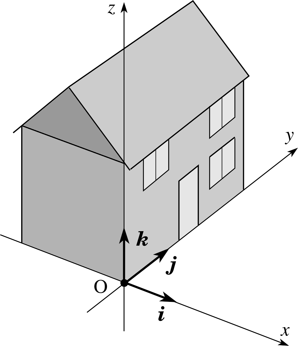
Figure 8 Fixed unit vectors in a right–handed coordinate system. (A coordinate system is said to be right-handed if a corkscrew rotated from the x–axis towards the y–axis advances in the direction of the z–axis.) The unit vectors i, j, and k provide directional information only. Although they are shown here located at the origin of the coordinate system, they may be attached to any fixed body placed at any point in the frame of reference.
Before explaining how to represent torques by vectors, it is worth reviewing some general definitions and properties of vectors. This is a diversion from the main subject of this module, but provides essential mathematical background. The main concepts we need to cover are those of unit vectors and vector products.
A unit vector is a vector of unit magnitude: its magnitude is not equal to 1 metre, but to the pure number 1, which has no units. This is rather an abstract idea, but it allows us to represent many other vectors in terms of unit vectors. For example, suppose that the unit vector i points along the x–direction. Then the vector (5 m) i represents a displacement of length 5 m in the x-direction and the vector (5 m s−1) i represents a velocity with speed 5 m s−1 in the x-direction. The unit vector i indicates direction, but contains no information about magnitude or units.
It is useful to define three unit vectors, i, j and k, which point, respectively, along the x–, y– and z–axes of a right–handed coordinate system (Figure 8). Then any position vector r = (x, y, z) can be expressed as a vector sum of x i, y j and z k:
r = x i + y j + z k
Any other vector, such as a force vector F = (Fx, Fy, Fz), can be represented in a similar way:
F = Fx i + Fy j + Fz k
Quantities like Fx i are called component vectors. These are genuine vectors with magnitude and direction and should not be confused with scalar quantities such as Fx, which are just called components_of_a_vectorcomponents.
Figure 20 See Answers T3, T4, T7 and T8. This shows a mast with one of its tie cords.
Question T7
In Question T3 and Figure 20 express the force vector exerted by the cord on the mast, in terms of unit vectors along the x–, y– and z–axes.
[For reference: Question T3. An aerial mast 5 m high is secured by a set of tie cords which are attached to the mast 1 m from the top. If each cord is secured to the ground 8 m from the mast and stretched to a tension of 120 N, find the magnitude of the torque exerted by a single cord about a fulcrum at the base of the mast.]
Answer T7
From Figure 20 we see that the tension T lies in the y–z plane, with no x–component. The y–component is T sin θ and the z–component is −T cos θ. In terms of unit vectors we have:
T = T sin θ j −T cos θ k
where T is 120 N and θ is 63.43°, so this gives:
T = (107.31 j − 53.67 k) N.
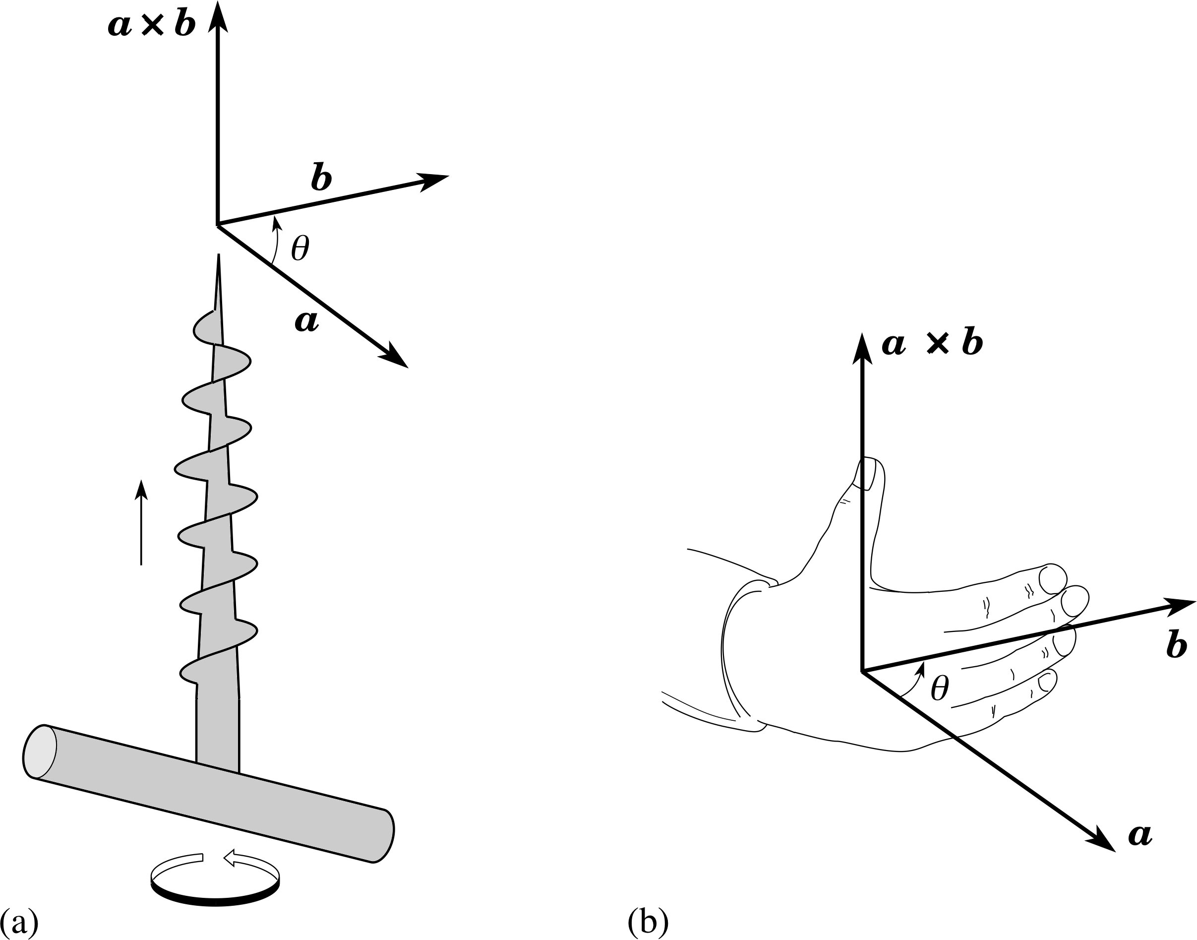
Figure 9 Defining the direction of the vector product a × b of two vectors a and b according to the corkscrew rule and the right–hand rule. (a) The corkscrew rule: when a corkscrew is turned from a to b through the smaller angle θ, the tip of the corkscrew advances in the direction of a × b. (b) The right–hand rule: when the fingers of the right hand are curled in the direction from a to b then the thumb points in the direction of a × b (rather than in the opposite direction).
The second concept we need is that of the vector product (sometimes called the cross product) of two vectors. i
Given any two vectors, a and b, which are inclined at an angle θ to one another, their vector product is written as a × b and has the following properties:
(i) it is a vector;
(ii) it has magnitude ab sin θ; i
(iii) its direction is perpendicular to both a and b and is defined equivalently either by a corkscrew rule (Figure 9a) or by the right–hand rule (Figure 9b)
Notice, in particular, that the order of the vectors in a vector product is important. If the order of the two vectors is reversed then the sign of the vector product is reversed:
b × a = − a × b
Also, the vector product of any two parallel vectors is zero
a × b = 0 (because θ = 0)
and, as a special case, the vector product of any vector with itself is zero
a × a = 0
3.2 The torque vector
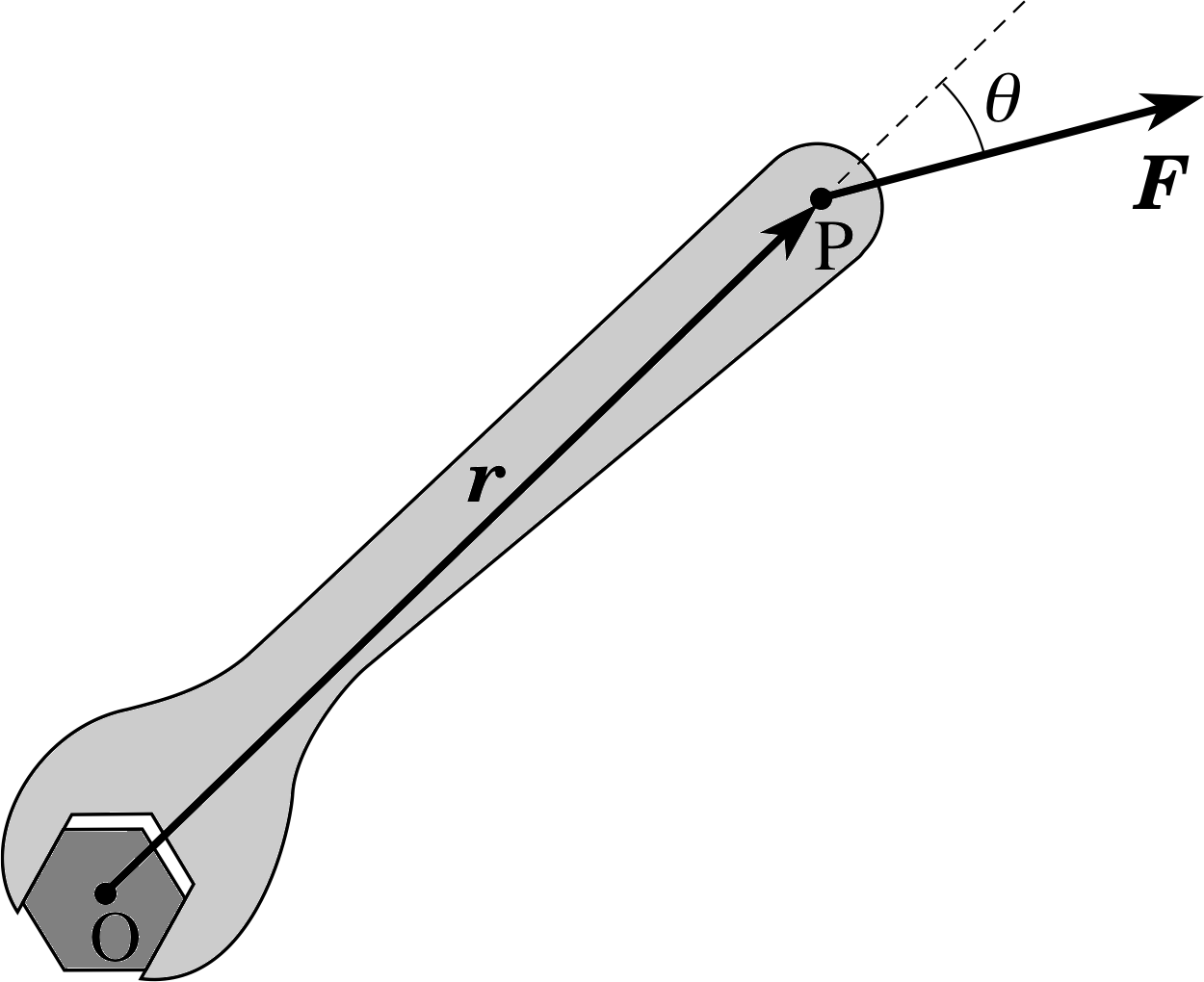
Figure 10 Representing torque by a vector. The z–axis, which points out of the page towards you, is the axis of rotation.
With these definitions of unit vectors and vector products in place, it is possible to return to the main issue of using vectors to represent torques. To specify a torque vector, we must define its magnitude and direction. The magnitude is easily dealt with – we just use the previous expression:
Γ = r F sin θ(Eqn 1)
To identify a sensible direction for the torque vector, it is helpful to consider again the case of the spanner and the nut shown in Figure 3a. Suppose we apply a force of constant magnitude F which acts at a constant angle θ (say 90°) to the handle of the spanner. Then the magnitude of the torque remains constant as the spanner turns. In the absence of other torques (such as those provided by friction) the nut would turn faster and faster about a fixed axis that runs through the centre of the nut, perpendicular to both the handle of the spanner and the applied force. Under such circumstances it makes sense to represent the torque by a constant vector Γ. We choose a Cartesian coordinate system with origin at the centre of the nut. The point of application of the force F is then represented by the position vector r. This notation is shown in Figure 10.
✦ In this situation of constant Γ, are the vectors r and F also constant?
✧ Neither r nor F are constant, since, as the spanner rotates, the force vector and the position vector each rotate with the spanner, so their directions change, even though their magnitudes stay constant.
✦ If the vector Γ stays constant in this situation then its magnitude and direction must stay constant. What direction for Γ can be chosen so that it remains fixed throughout the rotation?
✧ The only direction, as the vectors r and F move in the plane of rotation, is along the axis of the rotation – this direction remains at 90° to both r and F, whatever their positions in the plane of rotation.
These considerations lead us to choose the direction of the torque vector Γ to be perpendicular to the plane containing F and r (i.e. along the axis of rotation of the nut).
It remains to be decided which of the two possible directions along the axis should be chosen for the torque vector. This is a matter of convention. The convention that is adopted is to use the corkscrew or right–hand rule so that a corkscrew turning from the direction of r to the direction of F advances in the direction of the torque.
Now let us review the elements in our definition of the torque vector: it has magnitude Γ = r F sin θ and a direction that is at 90° to both r and F. This fits in precisely with the definition of a vector product (Subsection 3.1). Thus the concept of a vector product gives us a very convenient way of defining the torque vector Γ.
The torque vector is defined as the vector product of the position vector r of the point of application of the force and the force vector F (in that order):
Γ = r × F(4)
This vector has magnitude Γ = r F sin θ (from Equation 1) and its direction is perpendicular to r and F in a sense determined by the corkscrew or right–hand rule.
It is worth noting that the torque vector of Equation 4 is defined relative to a given point – the origin of coordinates used to specify the position vector r. This origin can be chosen arbitrarily and need not lie on the axis of rotation. This is useful because one does not always know, at the outset, what the axis of rotation is!
Like any other vector quantity, a torque vector can be represented by a directed straight line segment. One sometimes sees curved arrows being used to indicate a sense of rotation, but a curved arrow should never be used to represent the torque vector itself, which should always be shown as a straight line with an arrow. The length of the line is proportional to the magnitude of the torque vector and the direction of the arrow is the direction of the torque vector. i
Figure 8 Fixed unit vectors in a right–handed coordinate system. (A coordinate system is said to be right-handed if a corkscrew rotated from the x–axis towards the y–axis advances in the direction of the z–axis.) The unit vectors i, j, and k provide directional information only. Although they are shown here located at the origin of the coordinate system, they may be attached to any fixed body placed at any point in the frame of reference.
Since torque is a vector, it must have definite components relative to the x–, y– and z–axes of the chosen Cartesian coordinate system. It is natural to ask what the relationship is between the components of the torque vector and the components of the position vector r = (x, y, z) and of the force vector F = (Fx, Fy, Fz). To answer this question it is helpful to write the position and force vectors in unit vector notation:
r = x i + y j + z k
F = Fx i + Fy j + Fz k
It follows that
Γ = r × F = (x i + y j + z k) × (Fx i + Fy j + Fz k)
This may be expanded as follows
Γ = xFx (i × i) + xFy (i × j) + xFz (i × k)
+ yFx (j × i) + yFy (j × j) + yFz (j × k)
+ zFx (k × i) + zFy (k × j) + zFz (k × k)
Since the unit vectors are mutually perpendicular and point along the axes of a right–handed Cartesian coordinate system (Figure 8) we have:
i × i = 0 i × j = k i × k = −j
j × i = −k j × j = 0 j × k = i(5)
k × i = j k × j = −i k × k = 0
so that
Γ = (yFz − zFy) i + (zFx − xFz) j + (xFy − yFx) k(6)
which provides an explicit expression for the components of the torque vector.
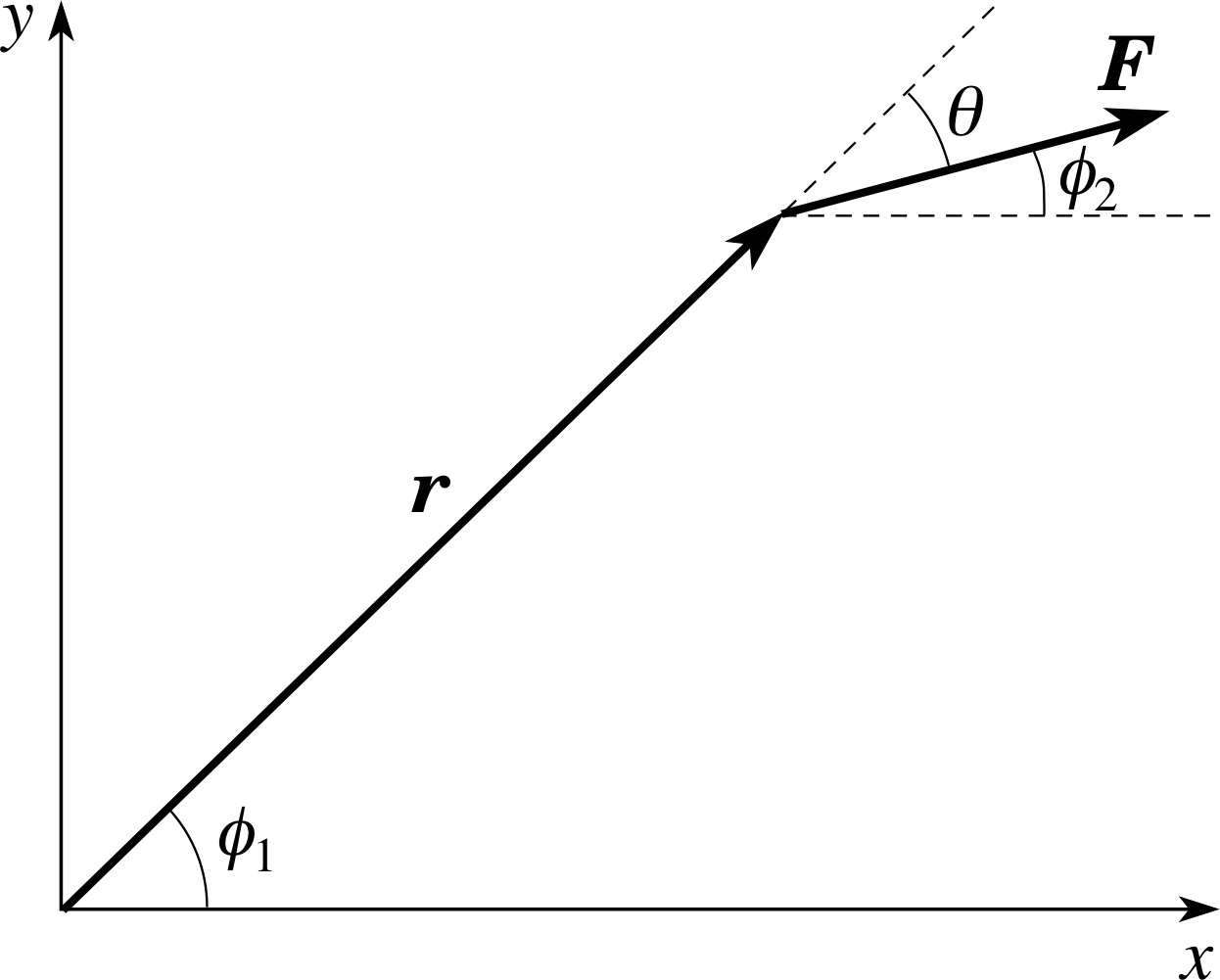
Figure 11 The relationship between the torque vector and the moment of a force.
Figure 10 Representing torque by a vector. The z–axis, which points out of the page towards you, is the axis of rotation.
It is interesting to compare the definition of the torque vector with our previous discussion of the moment of a force in the context of coplanar forces. In the situation shown in Figure 10, the right–hand rule immediately gives a torque vector of magnitude r F sin θ that points away from you (i.e. along the negative z–axis). The x– and y–components of the torque vector are therefore zero, while the z–component is equal to −r F sin θ.
This calculation can also be carried out using components, with the aid of Figure 11. Since z = 0 and Fz = 0 we have Γx = Γy = 0.
We also find that
Γz = xFy − yFx = r cos(ϕ1) F sin(ϕ2) − r sin(ϕ1) F cos(ϕ2)
Γz = Fr (sin ϕ2 cos ϕ1 − cos ϕ2 sin ϕ1) = F r sin(ϕ2 − ϕ1) = −F r sin θ
as before. Compare this with the moment of the force, which is easily seen to be −F r sin θ (the moment is negative because the force tends to induce a clockwise rotation). This example illustrates a general point:
In the special case of coplanar forces, where torques are conveniently represented by moments of forces, each moment can be interpreted as the component of the torque vector along an axis perpendicular to the plane of the forces. The other components of the torque vector vanish.
When a number of coplanar forces act on a body, the resultant moment is found by adding all the moments together, taking account of their signs. More generally, the turning action of each force is represented by a torque vector and it is necessary to combine these torque vectors to find the net turning effect of all the forces. How should this be done? The answer is remarkably simple: the net turning effect is found simply by taking the vector sum of all the individual torque vectors
Thus, if the individual torque vectors are Γ1, Γ2, ... we form the resultant torque vector
Γ = $\displaystyle \sum_n$ Γn = Γ1 + Γ2 + ...(7)
and this represents the net torque due to all the forces. The vector addition can be performed geometrically, using the triangle rule, or algebraically, by adding components like those appearing in Equation 6.
Γ = (yFz − zFy) i + (zFx − xFz) j + (xFy − yFx) k(Eqn 6)
Rotational equilibrium then requires the resultant torque vector to vanish:
Γ = $\displaystyle \sum_n$ Γn = 0(8)
Study comment Because this module concentrates on uni–axial rotation, it is generally concerned with coplanar forces which are efficiently dealt with using moments, as in Subsection 2.3. This should not obscure the fact that the representation of torques by vectors has a more fundamental and general significance: no matter what forces are acting, it is always possible to find the corresponding torque vectors and then use vector addition to find the resultant torque vector. More general methods can be used in cases where the axis of rotation changes its orientation. These methods are introduced in the FLAP module dealing with angular momentum.
Figure 20 See Answers T3, T4, T7 and T8. This shows a mast with one of its tie cords.
Question T8
(a) Using the axes you have drawn for Question T7 (Figure 20), represent the position vector of the point of attachment of the cord to the mast in unit vector notation, choosing the base of the mast as the origin of coordinates. (b) Now find the vector torque of the force about the base of the mast, in unit vector notation.
Answer T8
(a) The coordinate axes are those shown in Figure 20; the position vector r of the point P of attachment of the cord to the mast is: r = 4 k m.
(b) The torque is then:
Γ = r × T = 4 k × (107.3 j − 53.67 k) N m = 429 (k × j) N m = −429 i N m3
This confirms that the torque is along the negative x–axis, as expected from the corkscrew rule or the right hand rule, with a size as given in Answer T3, i.e. 429 N m.
4 Rotational kinematics
In linear motion it is possible to develop a set of kinematic i equations, called the uniform acceleration equations, which describe how a body’s position and velocity depend on time when it is undergoing uniform acceleration. As a second stage it is possible to understand the process of acceleration itself in terms of the resultant force acting on the body of mass m.
The equations of dynamics which describe this are Newton’s laws of motion. In this approach, force is that quantity which causes acceleration and uniform motion occurs when there is no resultant force acting on the body. This analysis can be extended to two– or three–dimensional motion by casting the uniform acceleration equations and Newton’s laws of motion in terms of vectors. In general, vector methods provide a powerful technique for extending results into three dimensions.
In this module we have been studying rotational motion rather than linear motion, but you may have seen many similarities to linear motion – for example, in the discussion of equilibrium (Subsection 2.5). Our task now is to draw out these similarities and then to apply the familiar ideas of linear motion to the new situation of rotational motion. In this section we will develop the equations of rotational kinematics in terms of angular position, angular speed, angular velocity and angular acceleration. In the next section we will consider rotational dynamics and develop the rotational equivalent of Newton’s laws of motion for the special case of uni–axial motion. We have already suggested that torques are responsible for changing the rotational state of a body, just as forces are for changing the uniform motion of a body. It should come as no surprise to you to find that torques are responsible for angular acceleration, just as forces are for acceleration in a straight line. However this is for Section 5!
Our first task in this section is to give a clearer definition of the basic terms describing angular motion and, in particular, to present them in vector form where possible.
4.1 Angular speed and angular velocity
It is easy enough to define the angular speed of a particle that moves in a circle. Figure 12 shows a point mass m moving in a circle of radius r in the x–y plane. The z–axis, which points out of the plane of the page (towards you), is the axis of rotation. The particle is at point P, with an angular position θ measured from the x–axis and an angular speed ω defined by
$\omega = \left\lvert\,\dfrac{d\theta}{dt}\,\right\rvert$ i
Clearly, the SI unit of angular speed is radian s−1. The speed υ of the particle along its circular path is determined by the radius of the circle and the angular speed:
$\upsilon = r\,\left\lvert\, \dfrac{d\theta}{dt}\,\right\rvert = r\omega $
Note that angular speed is the magnitude of the rate of change of angular position; it is a positive quantity and, of itself, contains no information about the axis of rotation or the sense of rotation around it (clockwise or anticlockwise).
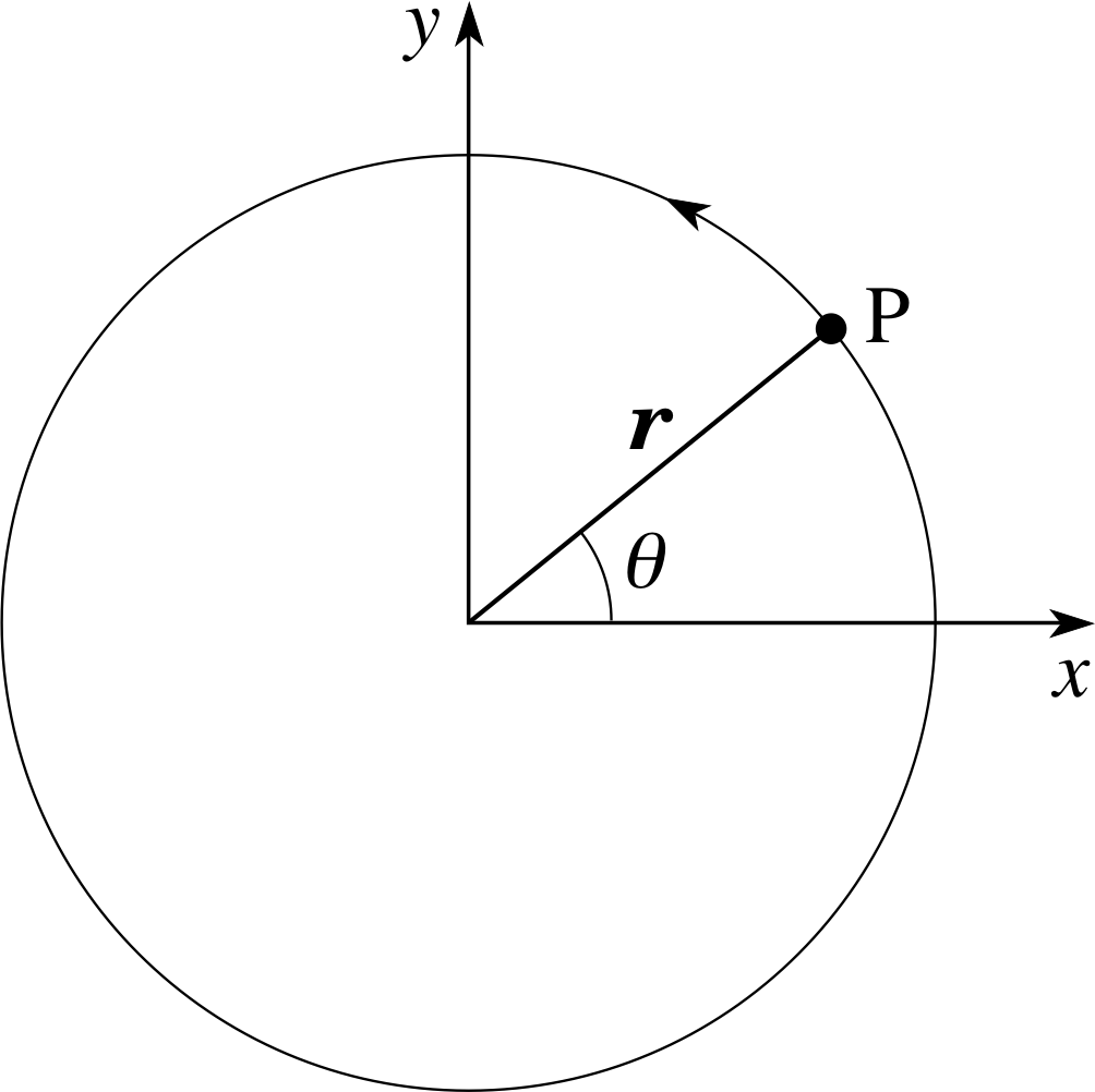
Figure 12 A particle moving in a circle. The (x, y) plane forms the plane of rotation and the z–axis points towards you. Looking down onto the (x, y) plane from the positive z–axis, the angle θ increases for anticlockwise rotations.
By analogy with the treatment of torques, we now investigate whether it is possible to give a more complete description of circular motion, by defining an angular velocity vector. The magnitude of the angular velocity vector is, of course, taken to be the angular speed ω, but what about its direction?
In Subsection 3.1 we introduced vector notation for torques and aligned the torque vector with the axis of the implied rotation. We made this choice because this was the only line which had a special significance for the rotation. As a matter of convention, we also used a corkscrew rule or a right–hand rule to determine the orientation of the torque vector along the axis, thereby providing a unique definition for the torque vector. Exactly the same considerations apply to the choice of a direction for the angular velocity vector; it is taken to be along the axis of rotation and in a direction defined by the right–hand grip rule. (Let the fingers of your clenched right hand follow the motion of the particle and your outstretched thumb will point along the angular velocity vector, rather than in the opposite direction.) Applying this rule to the motion shown in Figure 12, the direction of the angular velocity vector is out of the page, towards you.
In terms of unit vectors, ω = ω k and this vector provides a complete description of the circular motion, encapsulating the rate of rotation (of magnitude ω), the orientation of the axis of rotation (along the z–axis) and the sense of rotation (anticlockwise as seen from the positive z–axis because ωz is positive).
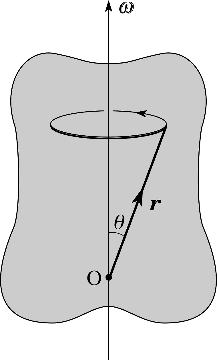
Figure 13 A rigid body spins about an axis that is fixed within it. With the origin located on the axis of rotation, the velocity vector of any particle within the body is given by the vector product of the angular velocity vector w and the particle’s position vector r.
The angular velocity vector is particularly useful when dealing with rigid bodies. Suppose that a rigid body rotates about an axis that is fixed within it, for example, passing through its centre of mass. Then, precisely because the body is rigid, each of its constituent particles has the same angular speed, axis of rotation and sense of rotation. Thus, each particle in the rigid body has the same angular velocity vector. It is therefore natural to think of the angular velocity vector as being a property of the rigid body as a whole. To illustrate the use of the angular velocity in this context, we will quote one famous formula. If a rigid body has angular velocity ω and its axis of rotation is fixed in space, the velocity υ of any one of its particles is given by a vector product:
for a rigid body rotating about a fixed axis
υ = ω × r(9)
where r is the position vector of the particle relative to an origin that lies on the axis of rotation.
Figure 13 indicates why Equation 9 is valid in this case.
The radius of orbit of the particle is r sin θ so its speed is (r sin θ) × ω, which is the magnitude of ω × r. You can check for yourself that the right–hand rule gives the correct direction for the velocity vector υ. i
The angular velocity vector provides a convenient and natural way to describe rotations. It turns out, for example, that if a spinning object is placed on a rotating platform (say, a CD spinning on the surface of the revolving Earth) the net effect of these two rotations is given by the vector sum of the two angular velocity vectors.
Figure 12 A particle moving in a circle. The (x, y) plane forms the plane of rotation and the z–axis points towards you. Looking down onto the (x, y) plane from the positive z–axis, the angle θ increases for anticlockwise rotations.
Question T9
Suppose that Figure 12 corresponds to the wheel of a car travelling along the negative x–axis at 100 km hr−1. The wheel diameter is 70 cm. Calculate:
(a) the speed (relative to the car) of a point on the outer edge of the wheel;
(b) the speed (relative to the road) of the point on the wheel which is in momentary contact with the road;
(c) the angular speed of the wheel;
(d) the angular velocity of the wheel (in unit vector notation).
State clearly which units you are using.
Figure 12 See Answer T9.
Answer T9
In each revolution of a wheel the distance travelled by the car is 2πr, where r is the radius of the wheel. The speed of the car is 100 × 1000 m/3600 s = 27.8 m s−1.
(a) This speed of 27.8 m s−1 must also be the speed of a point on the circumference.
(b) The point on the wheel which is in momentary contact with the ground is being carried forward with the overall speed of the vehicle but has an opposite motion due to its rotation – so it is momentarily at rest relative to the road. You may find this surprising, but the tyres would soon wear out if it weren’t true!
(c) We use υ = rω to find ω = υ/r = 27.8 m s−1/0.35 m = 79.4 rad s−1.
(d) Figure 12 can be used to represent the situation, with the circular path becoming the wheel. Since ω is along the z–axis, we have ω = 79.41k rad s−1.
4.2 Angular acceleration
Angular acceleration α, is defined as the rate of change of angular velocity with time:
$\boldsymbol{\alpha} = \dfrac{d\boldsymbol{\omega}}{dt}$(10)
This is clearly a vector quantity with SI units of rad s−2. Angular acceleration can take place either because the angular speed ω changes, or because the direction of the axis of rotation changes (or possibly because both changes occur together). In this module, we are concerned mainly with uni–axial rotation, in which the axis of rotation maintains a fixed orientation. Under such circumstances, angular acceleration can only be caused by a change in angular speed. In particular, if the fixed axis of rotation is taken to be the z–axis, the angular acceleration vector has components
αx = 0, αy = 0 and αz = $\dfrac{d\omega_z}{dt}$(11)
Notice that, even in the case of uni–axial motion, we still keep the x, y and z subscripts. This allows us to distinguish between the scalar component αz (which may be positive or negative) and the magnitude α (which cannot be negative). It also helps to ease the transition from uni–axial rotation to more general situations.
In the spirit of this notation we have also written
$\omega_z = \dfrac{d\theta_z}{dt}$
where θz is the angle of rotation around the z–axis. This is consistent with our treatment of linear motion, where we use symbols such as sx or υx even when the motion was known to be confined to the x–axis.
There is a close parallel between uni–axial rotation and linear translation which is seen most clearly in the equations that describe uniform angular acceleration about a fixed axis (αz = constant), and those that describe uniform linear acceleration along a fixed line (ax = constant).
| Linear motion with uniform translational acceleration |
Uni-axial rotational motion with uniform angular acceleration |
|---|---|
| υx = dx/dt | ωz = dθz /dt |
| ax = dυx /dt | αz = dωz /dt |
| υx = ux + axt | ω z = μz + αzt |
| ∆x = (ux + υx)t/2 | ∆θz = (μz + ωz)t/2 |
| υx2 = ux2 + 2a∆xx | ωz2 = μz2 + 2αz ∆θz |
| ∆x = uxt + axt2/2 | ∆θz = μzt + αzt2/2 |
Table 1 compares the two sets of equations. Here, ∆x represents the linear displacement along the x–axis (sometimes denoted by sx) and ∆θz represents the angular displacement around the z–axis. The initial and final linear velocities are ux and υx and the initial and final angular velocities are μz and ωz. The constant linear acceleration is ax, the constant angular acceleration is αz and the time elapsed is t. The first two rows are definitions. The last four equations in the right–hand column follow from the definitions of ωz and αz for the same reasons that the last four equations in the left–hand column follow from the definitions of υx and ax.
Note The similarity between uni–axial rotation and linear translation is impressive – so impressive that you might be tempted to take the analogy one stage too far. It is essential to realize that our discussion has been hedged by restrictions which confine attention to uni–axial rotations. If these restrictions are lifted, significant differences between translational and rotational dynamics can arise. To illustrate this point, I shall give an example. You have seen that translational equilibrium implies zero resultant force and rotational equilibrium implies zero resultant torque. The first of these conditions can be reversed: zero resultant force certainly guarantees translational equilibrium. But the same cannot be said for torques! It is possible to have zero resultant torque and yet fail to have rotational equilibrium (in the sense that we have defined it). For example, if you throw a rapidly spinning (preferably unbreakable!) plate into the air, its axis of rotation may appear to wobble. Because gravity acts through the centre of mass, there is no torque about any axis through the centre of mass, yet the plate does not rotate steadily round an axis of fixed orientation. We need a new concept – angular momentum – which is introduced elsewhere in FLAP and will help to explain such phenomena. It will then be possible to draw a deeper analogy between angular and linear motion, based on similarities between linear and angular momentum.
Question T10
Suppose the car in Question T9 (travelling along the negative x–axis at 100 km hr−1 with a wheel diameter of 70 cm) comes to rest with a uniform linear deceleration in 6 s. Calculate: (a) the angle swept out by each wheel in 6 s; (b) the magnitude of the angular acceleration of the wheels; and (c) the angular speed after 3 s.
Answer T10
(a) Since the wheel rotates about the z–axis we write the equations of uniform angular acceleration with z subscripts. Using ∆θz = (μz+ ωz)t/2 we obtain
∆θz = (79.4 + 0) rad s−1 × 3 s = 238 rad
(b) The kinematic equation ωz = μz + αzt applies because the acceleration is uniform. Clearly ωz = 0 and μz = 79.4 rad s−1 from Answer T9.
Soαz = −79.4 rad s−1/6 s = −13.2 rad s−2. The magnitude of the angular acceleration is therefore 13.2 rad s−2.
(c) To find the angular speed after 3 s we can use the equation:
ωz = μz + αzt = 79.4 rad s−1 −13.2 rad s−2 × 3 s = 39.8 rad s−1.
5 Introducing the laws of rotational dynamics
Now that we have established the kinematic equations of uni–axial uniform angular acceleration, we return to the question of the origins of angular acceleration. You will recall that the linear acceleration of a body depends not only on the resultant force but also on an intrinsic property of the body – its inertial mass (usually called mass for short) – which measures the body’s intrinsic reluctance to accelerate. Newton’s second law allows us to calculate the acceleration produced by a given resultant force acting on a given mass. In uni–axial rotational motion we have identified torque as the driving mechanism of angular acceleration, analogous to force in linear motion. As you might expect, there is a quantity analogous to mass which measures rotational inertia – the reluctance of the body to undergo angular acceleration about a given axis. This quantity, which is called the moment of inertia, will be defined in the next subsection and used to obtain a rotational analogue of Newton’s second law.
5.1 Moment of inertia
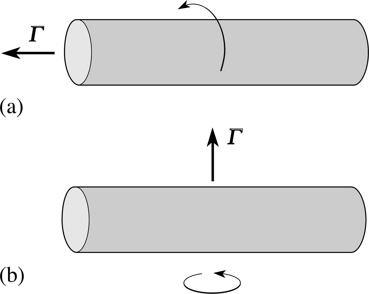
Figure 14 A rod is acted on by a torque which spins it (a) around its long axis, (b) perpendicular to its long axis.
Suppose that we have a long cylindrical rod which is initially at rest, and that we apply a torque to it. If the resultant torque vector is parallel to the rod, the rod will start to rotate around its long axis (Figure 14a). We could carry out a series of experiments investigating the link between the resultant torque applied and the angular acceleration of the rod. These would show that the initial angular acceleration is:
- 1
-
proportional to the magnitude of the torque;
- 2
-
dependent on the nature of the rod: large, dense rods tend to have lower angular accelerations.
We could also apply the torque so that the resultant torque vector is perpendicular to the rod. In this case, the rod starts to spin end over end (Figure 14b) and we can make a third observation:
- 3
-
For a torque of given magnitude the angular acceleration of the rod is smaller when the torque is perpendicular to the rod than when it is parallel to it.
Question T11
In trying to model this situation mathematically, a theoretician suggests the following equation: Γ = mα where m is the mass of the body. Which of the observations 1 to 3 above is inconsistent with the suggestion?
Answer T11
Observation 3 is inconsistent with the claimed equation. It tells us that the angular acceleration of the rod depends on the direction in which the torque acts, relative to the long axis of the rod. This does not agree with the suggested equation, which gives an acceleration of magnitude Γ/m irrespective of the direction of the torque.
From Answer T11 it is clear that rotational inertia cannot be measured by a single property of the body (like its mass) because it depends on how the mass of the body is distributed relative to the axis of rotation. We can see this principle at work using the following thought-experiment.
Imagine a roundabout in a children’s playground, complete with some volunteer children to use it. Suppose that we try to push the roundabout up to speed, first with an empty roundabout, then with the children on board, huddled near the centre, and finally with the same children, but now around the outer circumference.
✦ If we apply our maximum torque to the roundabout in each case, in which of these three situations would the magnitude of the angular acceleration be greatest and in which one would it be smallest?
✧ The first situation, with the empty roundabout, would have the largest magnitude of angular acceleration; the third situation, with the children around the circumference, would have the smallest magnitude of angular acceleration.
The roundabout example shows that the rotational inertia is larger when the mass is larger (i.e. with the children on board) and is larger if the mass is distributed further from the axis of rotation. We can now define moment of inertia. Our definition will apply to any body that rotates about an axis that is fixed within the body and maintains a fixed orientation (the uni–axial case). Suppose that the resultant torque acting on the body is Γ and that the angular acceleration is α. Then the moment of inertia of the body about the given axis is the proportionality constant I in the equation
Γ = Iα = I$\dfrac{d\boldsymbol{\omega}}{dt}$(12)
Equation 12 expresses Newton’s second law of motion for uni–axial rotational motion. The similarity between Equation 12 and Newton’s second law of motion for linear motion, F = ma = mdυ/dt, is striking. As we suggested in Subsection 2.5 there is a role for torque in rotational motion which mirrors that of force in linear motion. Here we also see that there is a role for moment of inertia in uni–axial rotational motion which mirrors that of mass in linear motion.
Question T12
(a) Prove that moment of inertia, as defined by Equation 12,
Γ = Iα = I$\dfrac{d\boldsymbol{\omega}}{dt}$(12)
has dimensions [M] [L2]. i (b) If a roulette wheel has a frequency of 1/2 a revolution per second, a moment of inertia about its axis of rotation of 25 kg m2 and takes 12 s to come to rest, calculate the magnitude of the torque acting on it during deceleration. (You may assume that its angular acceleration is constant.)
Answer T12
(a) Using Equation 12,
Γ = Iα = I dω/dt(Eqn 12)
and taking the magnitudes only we have Γ = Iα and so I = Γ/α.
In terms of base quantities, the dimensions of torque Γ are those of force × distance = [M][L][T−2] [L] = [M][L2][T−2]. The dimensions of angular acceleration α are [T−2] since angular measure is dimensionless.
Finally, the dimensions of moment of inertia I are [M][L2][T−2]/[T−2]= [M][L2].
(b) Suppose that the roulette wheel is initially spinning so that its angular velocity vector points along the upward z–axis. The initial angular velocity is then μz = 2πf = 2π/2 = π rad s−1 and the final angular velocity is ωz = 0. The angular acceleration can be found using ωz = μz+ αzt which gives
αz = −μz /t = −π rad s−1/2 s = −0.262 rad s−2
Finally, the retarding torque is given by
Γz = Iαz = 25 kg m2 × −0.262 rad s−2 = −6.55 N m.
The magnitude of the torque is therefore 6.55 N m.
Answer T12 establishes the dimensions of moment of inertia, but we need a formula for calculating moment of inertia. Dimensional analysis cannot be relied upon to do this because it leaves out dimensionless constants such as 1/2 or π, and also there could be other cancellations of dimensions of the quantities involved.
Figure 12 A particle moving in a circle. The (x, y) plane forms the plane of rotation and the z–axis points towards you. Looking down onto the (x, y) plane from the positive z–axis, the angle θ increases for anticlockwise rotations.
Question T13 i
Look again at Figure 12 and now suppose that it represents a firework exhibit. A rocket is strapped to a small platform of mass m at P and OP is an arm of negligible mass, free to rotate about O without friction. The firework itself has negligible mass and is placed such that it produces a thrust of constant magnitude F, perpendicular to the arm at P and so tangential to the circle of the motion produced. Suppose that the arm is initially at rest when the rocket ignites.
(a) Show that the kinetic energy of the platform can be written as
Ekin = ½ mr2ω2
and that the rate of change of kinetic energy is
$\dfrac{dE_{\rm{kin}}}{dt} = mr^2\omega\alpha$
(b) Find an expression for the moment of inertia by equating $\dfrac{dE_{\rm{kin}}}{dt}$ with the power input by the thrust
$P=\dfrac{\Delta W}{\Delta t} = \it{\Gamma}\,\left |\dfrac{\Delta \phi}{\Delta t}\right | = \it{\Gamma} \omega$(Eqn 3)
Answer T13
(a) Since υ = rω the kinetic energy is Ekin = ½mυ2 = ½mr2ω2. The rate of change of kinetic energy is found by differentiating this expression with respect to time. Since m and r are constant and dω/dt = α, this gives
dEkin/dt = mr2ω α
(b) The rate of change of kinetic energy must equal the power input so Equation 3,
$P=\dfrac{\Delta W}{\Delta t} = \it{\Gamma}\,\left\lvert\dfrac{\Delta \phi}{\Delta t}\right\rvert = \it{\Gamma}\omega$(Eqn 3)
gives dEkin/dt = mr2ωα = Γω. Thus, Γ = mr2α and comparing this with Equation 12,
Γ = Iα = I dω/dt(Eqn 12)
allows us to identify the moment of inertia as I = mr2.
It follows from the answer to Question T13 that:
for a point mass m rotating at a distance r from the axis of rotation, the moment of inertia is
I = mr2(13)
In principle, Equation 13 forms the basis for calculating the moment of inertia of any body about any fixed axis, since any body can be regarded as being composed of a collection of point masses at various radii of rotation about the axis. Suppose an extended rigid body is rotating about an axis at an angular speed ω. We can regard the body as being composed of a large number of particles (say, N) each rotating round the same axis with the same angular speed ω.
If particle i has mass mi and is at distance ri from the axis of rotation, then its contribution to the moment of inertia is Ii = miri2. The total moment of inertia is then found by summing over all the particles so
for an extended body $\displaystyle I = \sum_{i=1}^N I_i = \sum_{i=1}^N m_i(r_i^2)$(14)
In practice, it is usually necessary to convert this sum into an integral. The details of this conversion will be dealt in Subsection 5.3 in the context of a specific example.
5.2 Rotational kinetic energy
Returning to Question T13 part (a), and using the result I = mr2 for the moment of inertia of a point mass, we can immediately obtain an expression relating the rotational kinetic energy of the particle to its moment of inertia and angular speed:
for a particle Erot = ½ Iω2
This expression for the rotational kinetic energy of a point mass is equally valid for a rotating extended body. To see why, let’s divide the body up (notionally) into individual particles and then add together the individual rotational kinetic energies of all these particles. Following an approach similar to that used in Subsection 5.1 we note that if particle i has mass mi and is at distance ri from the axis of rotation, then its contribution to the kinetic energy is ½ miri2ω2. The total rotational kinetic energy is then found by summing over all the particles to give
$\displaystyle E_{\rm{rot}} = \sum_{i=1}^N I_i \textstyle \frac{1}{2}m_ir_i^2\omega^2$
Using the fact that all particles in a rigid body have the same angular speed ω, together with Equation 14,
for an extended body $\displaystyle I = \sum_{i=1}^N I_i = \sum_{i=1}^N m_i(r_i^2)$(Eqn 14)
for the total moment of inertia I of the body, we finally obtain
for an extended body Erot = ½ Iω2(Eqn 15)
Sometimes objects move through space and rotate at the same time. It is therefore useful to know that the kinetic energy of any rigid body can be found by adding the translational kinetic energy of its centre of mass to the rotational kinetic energy associated with instantaneous rotation about an axis through the centre of mass.
5.3 Examples of moment of inertia and rotational kinetic energy
Study comment This subsection shows how moments of inertia can be calculated in some simple cases for rotating bodies. The methods of integral calculus are used and will be meaningful only if you have had some previous experience of this technique. i
You should remember that although a body has only one mass, it has an infinite number of moments of inertia, depending on the axis of rotation. The moment of inertia of a body should never be quoted without also giving the axis of rotation. For example, if we support a bicycle wheel from its rim with a screwdriver and rotate it about that axis, the moment of inertia is much larger than with its normal axis of rotation since more of its mass is further from the axis of rotation.
A homogeneous thin–walled cylinder (or ring) about its central axis
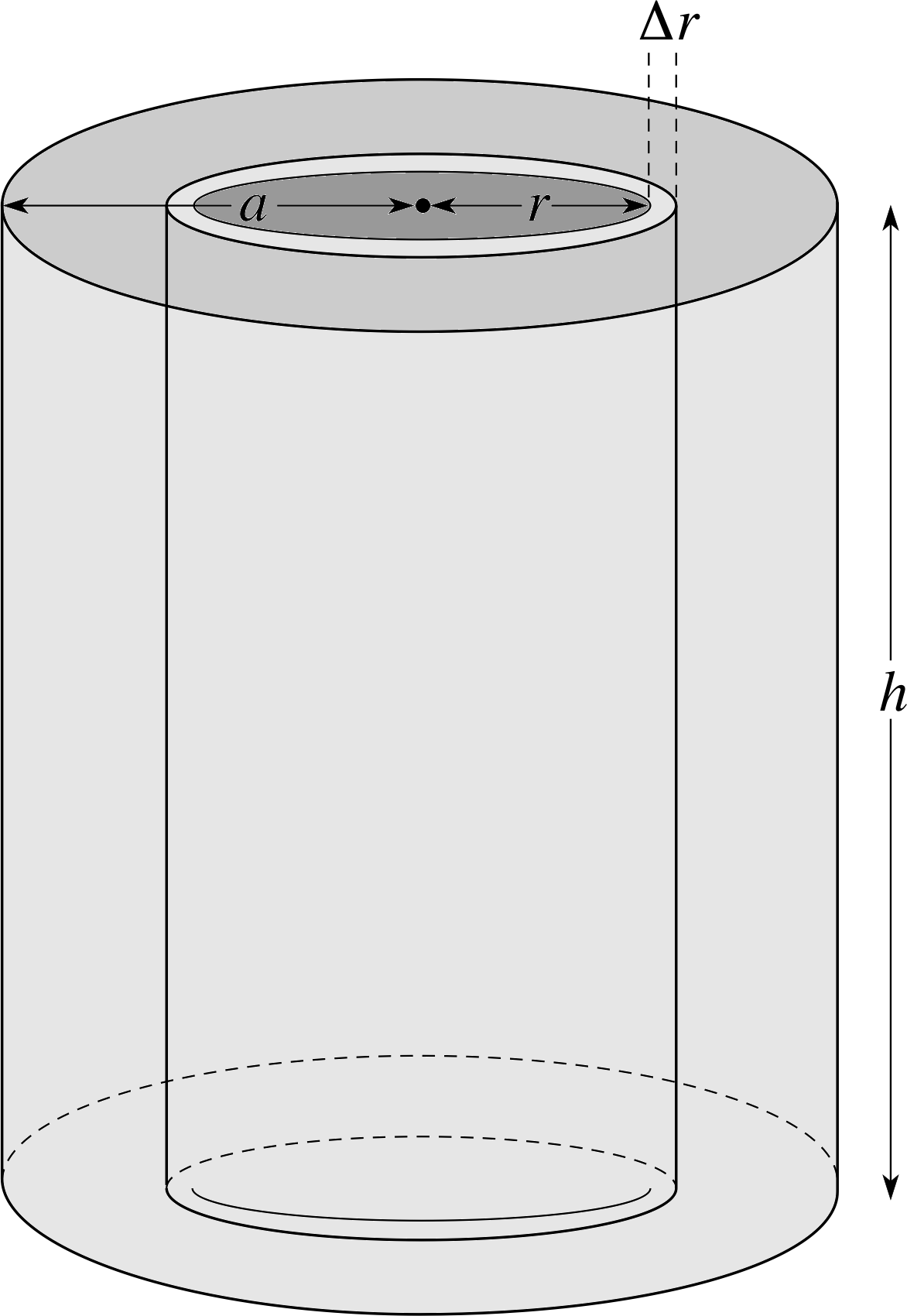
Figure 15 Moment of inertia of a solid cylinder of radius a about its central axis.
A thin–walled cylinder has all its mass elements at the same distance from the central axis of rotation. If this distance is a and the mass of the thin–walled cylinder is M then Equation 14 immediately gives:
For a homogeneous thin–walled cylinder about its central axis
$\displaystyle I = \sum_{i=1}^N I_i = \sum_{i=1}^N m_i(r_i^2) = a^2\sum_{i=1}^N m_i = Ma^2$(16)
(Exactly the same formula applies for a ring about a central axis, since a ring is just a short thin–walled cylinder and the height of the cylinder does not appear in Equation 16).
A homogeneous solid cylinder (or disc) about its central axis
A solid cylinder of height h and radius a can be regarded as being formed from a set of concentric thin–walled cylinders (see Figure 15). A typical thin–walled cylinder from this set has radius r, height h and thickness ∆r so its volume is πrh∆r. Taking the density of the cylinder to be ρ, the mass of each thin–walled cylinder is ρ × πrh∆r and its moment of inertia is ρ × 2πrh∆r × r2 (Equation 16).
$\displaystyle I = \sum_{i=1}^N I_i = \sum_{i=1}^N m_i(r_i^2) = a^2\sum_{i=1}^N m_i = Ma^2$(Eqn 16)
The moments of inertia of all the thin–walled cylinders must now be added together (Figure 15). We should consider the limiting case where the thickness of each thin–walled cylinder tends to 0 and the number of thin–walled cylinders tends to infinity.
Under these circumstances, the sum becomes an integral and the moment of inertia of the solid cylinder becomes
$\displaystyle I = \int_0^a \rho 2\pi r^3 h\,dr = 2\pi\rho h \int_0^a r^3\,dr = 2\pi\rho h \left [\dfrac{r^4}{4}\right ] = \dfrac{\pi\rho h a^4}{2}$
Since the mass of the cylinder is M = ρ × πa2h we can write I as:
For a homogeneous solid cylinder about its central axis:
$I = \dfrac{\pi\rho h a^4}{2} = \dfrac{(\pi a^2\rho h)a^2}{2} = \frac{1}{2}Ma^2$(17)
The same formula also applies to a flat disc about its central axis, since a disc is just a short cylinder and the height of the cylinder does not appear in Equation 17.
Similar methods can be applied to calculate the moment of inertia of other shapes with other axes of rotation, although the calculation is often more difficult. i
Figure 16 gives some examples for homogeneous bodies rotating about highly symmetric axes.
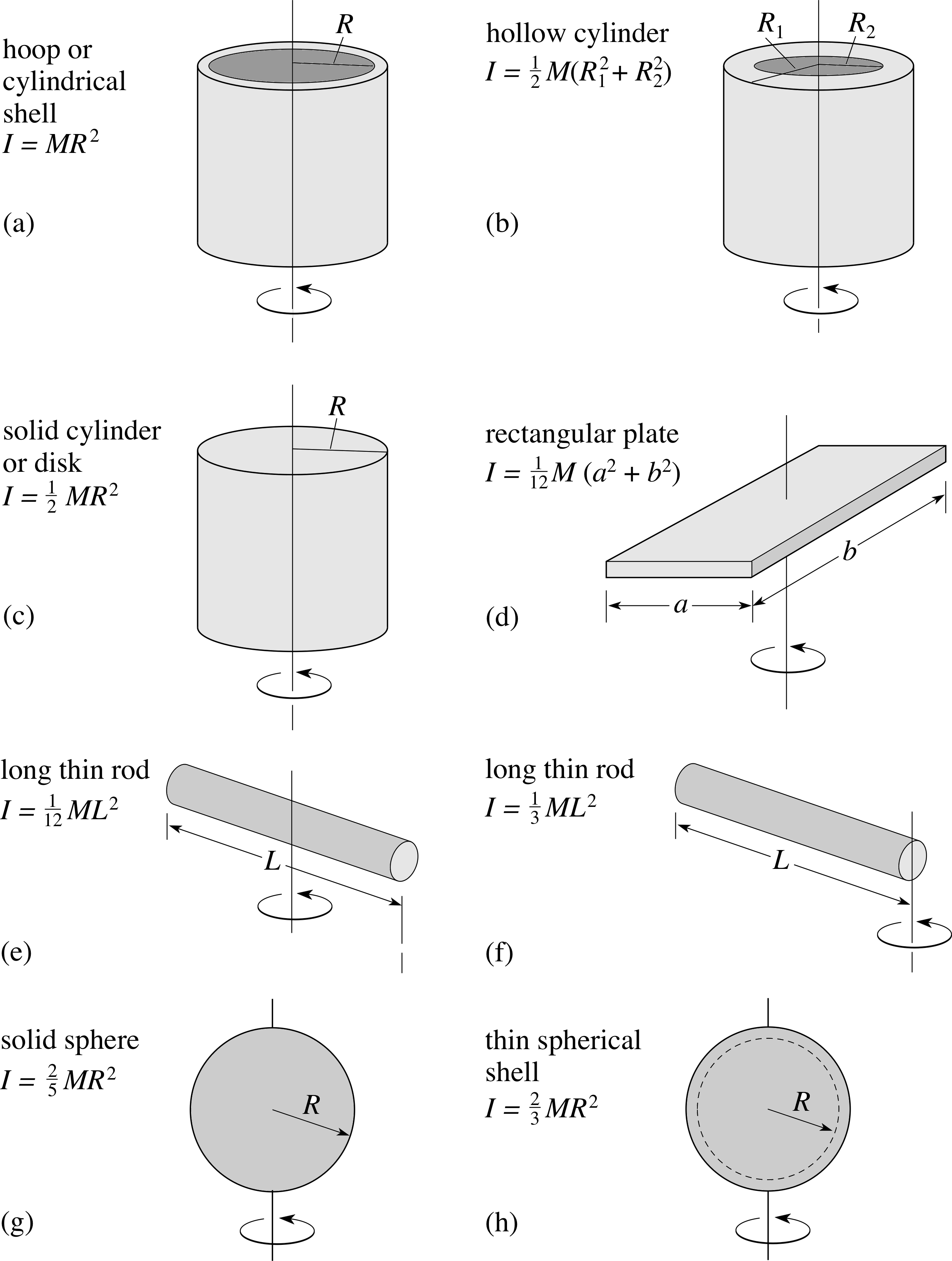
Figure 16a-h Moments of inertia of some homogeneous bodies about indicated axes.
Although we will not discuss details here, there are a few concepts and rules which can simplify the calculations and use of these moments of inertia.
- 1
-
The moment of inertia I of a real extended body of mass M rotating about a given axis is sometimes represented by an equivalent point mass of the same mass M, rotating with the same moment of inertia I about the same axis. In order to secure this equivalence the point mass must be placed a special distance k from the axis, where I = Mk2. The distance k is called the radius of gyration of the body and its use often simplifies the algebra of rotational dynamics.
- 2
-
The combined moment of inertia of several objects about the same axis, for example the wheels and axle of a car, is just the sum of the moments of inertia of the individual objects. For example, to calculate the moment of inertia of a hollow cylinder with thick walls, we may subtract the moment of inertia of an imaginary cylindrical plug which would fill the hollow part, from the moment of inertia of a solid cylinder.
- 3
-
If the moment of inertia of a body about an axis running through its centre of mass is Icm then the moment of inertia about any axis parallel to this, but displaced by a distance b, is given by I = Icm + Mb2.
The last result is called the parallel–axis theorem. It can be used, for example, to calculate the moment of inertia of a cylinder about an axis of rotation given by its line of contact with a surface. This is appropriate because, if the cylinder rolls without slipping, the line of contact is instantaneously at rest (see Answer T9) and so can be thought of as the instantaneous axis of rotation.
It is perhaps more normal to regard the motion of a rolling cylinder as comprising a translation of its centre of mass, accompanied by a rotation about a horizontal axis through the centre of mass. It is important to realize that either this or the line of contact approach will give the same answers to any given problem. For example, if a wheel of radius a is rolling, without slipping, at a speed υ, the angular speed of rotation is ω = υ/a. If the moment of inertia about the central axle is Icm and the mass of the wheel is M, the moment of inertia about the instantaneous line of contact with the ground is found using the parallel–axis theorem. This gives
Icontact = Icm + Ma2
so that the kinetic energy is
½ Icontactω2 = ½ (Icm + Ma2)ω2 = ½ Icmω2 + ½ Maω2 = ½ Icmω2 + ½ Mυ2
We can recognize this as the sum of the kinetic energy of rotation of the wheel about its axle and the kinetic energy of translation of the centre of mass, so agreement is reached. Take care if using the instantaneous line of contact approach: the above comparison makes it clear that this approach automatically includes the translational kinetic energy – it would be a mistake to add it in again!
Question T14
We may idealize a car wheel as a solid flat disc of mass 12 kg and diameter 60 cm.
(a) Calculate its moment of inertia about an axis parallel to its central axis and through its point of instantaneous contact with the ground.
(b) Calculate its radius of gyration.
(c) Calculate its kinetic energy when it is rotating at 3 revolutions per second.
Answer T14
(a) Suppose the wheel has mass M and radius a and that Icm is its moment of inertia about the central axle. Using the parallel–axis theorem we then find Icm = Icm + Ma2 = Ma2/2 + Ma2 = 3Ma2/2 which gives
Icm = 3Ma2/2 = 3 × 12 kg × (0.3 m)2/2 = 1.62 kg m2
(b) The radius of gyration k is defined by: I = Mk2 = 1.62 kg m2 and so k = (I/M)1/2 = (1.62 kg m2/2 kg)1/2 = 0.367 m. The moment of inertia of the wheel about the line of contact of the wheel on the ground is the same as if the mass of the wheel were concentrated 0.367 m from this axis.
(c) The total kinetic energy (i.e. rotational motion about the contact axis or the sum of translational centre of mass motion and rotational motion about the centre of mass) is given by: Ekin = Icmω2/2 = Mk2ω2/2.
The angular speed is ω = 2πf = 18.85 rad s−1 so the kinetic energy is:
Ekin = Mk2ω2/2 = 12 kg × (0.367 m)2 × (18.85 rad s−2)2/2 = 287 J
6 Closing items
6.1 Module summary
- 1
-
Torque measures the turning effect of a force about an axis or fulcrum. The magnitude of the torque Γ is the product of the magnitude of the force F and the perpendicular distance between the axis and the line of action of the force. This can be written as Γ = r F sin θ = F d.
- 2
-
The work done when a constant torque turns an object through a small angle is equal to the product of the magnitude of the torque and the angle.
- 3
-
The centre of mass of a body is the unique point such that any force directed through the point produces translation of the body but no rotation. The centre of mass moves through space just like a particle that experiences the resultant external force acting on the body.
- 4
-
A couple is a combination of two opposing forces of equal magnitudes which produces rotation without translation.
- 5
-
A body is said to be in translational equilibrium if its centre of mass remains at rest or moves with constant velocity. It is said to be in rotational equilibrium if it does not rotate, or rotates at a constant rate about an axis that passes through the centre of mass and maintains a fixed orientation. Mechanical equilibrium entails both translational and rotational equilibrium.
- 6
-
For translational equilibrium, the resultant force must be zero and for rotational equilibrium the resultant torque must be zero.
- 7
-
When a body is acted on by a set of coplanar forces, each torque can be represented by the moment of a force. This is given by the magnitude of the torque, together with a sign which indicates the sense of the implied rotation (anticlockwise usually being taken as positive).
- 8
-
Any vector can be represented in terms of unit vectors in the directions of the coordinate axes, usually written as i, j and k.
- 9
-
The vector product of two vectors a and b is written as (a × b) and is a vector whose magnitude is a b sin θ, where θ is the smaller angle between the two vectors. The direction of the vector product (a × b) is perpendicular to both a and b in a sense defined by a corkscrew or right–hand rule. This definition means that (b × a) = −(a × b).
- 10
-
In general, torque is represented by the torque vector Γ = r × F, which is the vector product of r, the position vector of the point of action of the force, and F, the force itself. This is also known as themoment of a forcemoment of the force.
- 11
-
The kinematic equations of uni–axial rotation have a formal analogy with those of uniform linear acceleration.
- 12
-
Newton’s laws of motion can be applied to Table 1uni-axial rotational motion. The resultant torque vector Γ is related to the angular acceleration α by Γ = Iα, where I is the moment of inertia of the body about the given axis of rotation.
- 13
-
The moment of inertia of a single particle of mass m at a distance r from the axis of rotation is mr2. The moments of inertia of bodies with simple shapes may be calculated by summation or by using integral calculus.
- 14
-
According to the parallel-axis theorem, if the moment of inertia of a body about an axis running through its centre of mass is Icm then the moment of inertia about any axis parallel to this, but displaced by a distance b, is given by I = Icm + Mb2.
- 15
-
The kinetic energy of a rigid body can be regarded as the sum of the translational kinetic energy of the centre of mass and the rotational kinetic energy around the centre of mass. Alternatively, if an axis in the body is instantaneously at rest, the kinetic energy of the body is just the rotational energy about this axis; Erot = ½ Iω2
6.2 Achievements list
Having completed this module, you should be able to:
- A1
-
Define the terms that are emboldened and flagged in the margins of the module.
- A2
-
Recall and use the expression Γ = r F sin θ = Fd, which gives the magnitude of the torque acting about a given axis.
- A3
-
Derive and use the law relating rotational work done to torque and angle described.
- A4
-
Apply the law of static moments to situations of rotational equilibrium.
- A5
-
Show how the vector product is defined, both diagrammatically and in terms of unit vectors.
- A6
-
Represent torque, angular velocity and angular acceleration as vectors, and show these diagrammatically in relation to the plane of rotation.
- A7
-
Calculate the magnitude and direction of a torque using vector products.
- A8
-
Recall and use the kinematic equations for uniform acceleration in linear motion and in uni–axial rotational motion and identify their similarities.
- A9
-
Describe the concept of rotational inertia and show in principle how the moment of inertia of an extended body is defined.
- A10
-
Use the parallel–axis theorem and the concept of the radius of gyration.
- A11
-
Recall and use the equation Γ = Iα = I (dω/dt), which corresponds to Newton’s second law of motion, as applied to uni–axial rotational motion.
- A12
-
Describe the concept of rotational kinetic energy and how it is related to the moment of inertia and the angular speed.
Study comment You may now wish to take the Exit test for this module which tests these Achievements. If you prefer to study the module further before taking this test then return to the topModule contents to review some of the topics.
6.3 Exit test
Study comment Having completed this module, you should be able to answer the following questions, each of which tests one or more of the Achievements.
Question E1 (A2 and A3)
Estimate the torque which you apply to the trunk of your body when you begin to sit upright, moving from a prone position, lying on your back. How much work do you do in sitting upright?
Answer E1
Suppose that the trunk of your body has mass 40 kg and that its centre of mass is 0.5 m from your hip-joint. The moment of this weight about your hip–joint when you are in a prone position is
Γ = Mgr ≈ 40 kg × 10 m s−2 × 0.5 m = 200 N m
The mechanical work done W is equal to the weight of your trunk multiplied by the vertical height h moved by the centre of mass. Thus
W = Mgh ≈ 40 kg × 10 m s−2 × 0.5 m = 200 J.
(Reread Subsections 2.1 and 2.2 if you had difficulty with this question.)
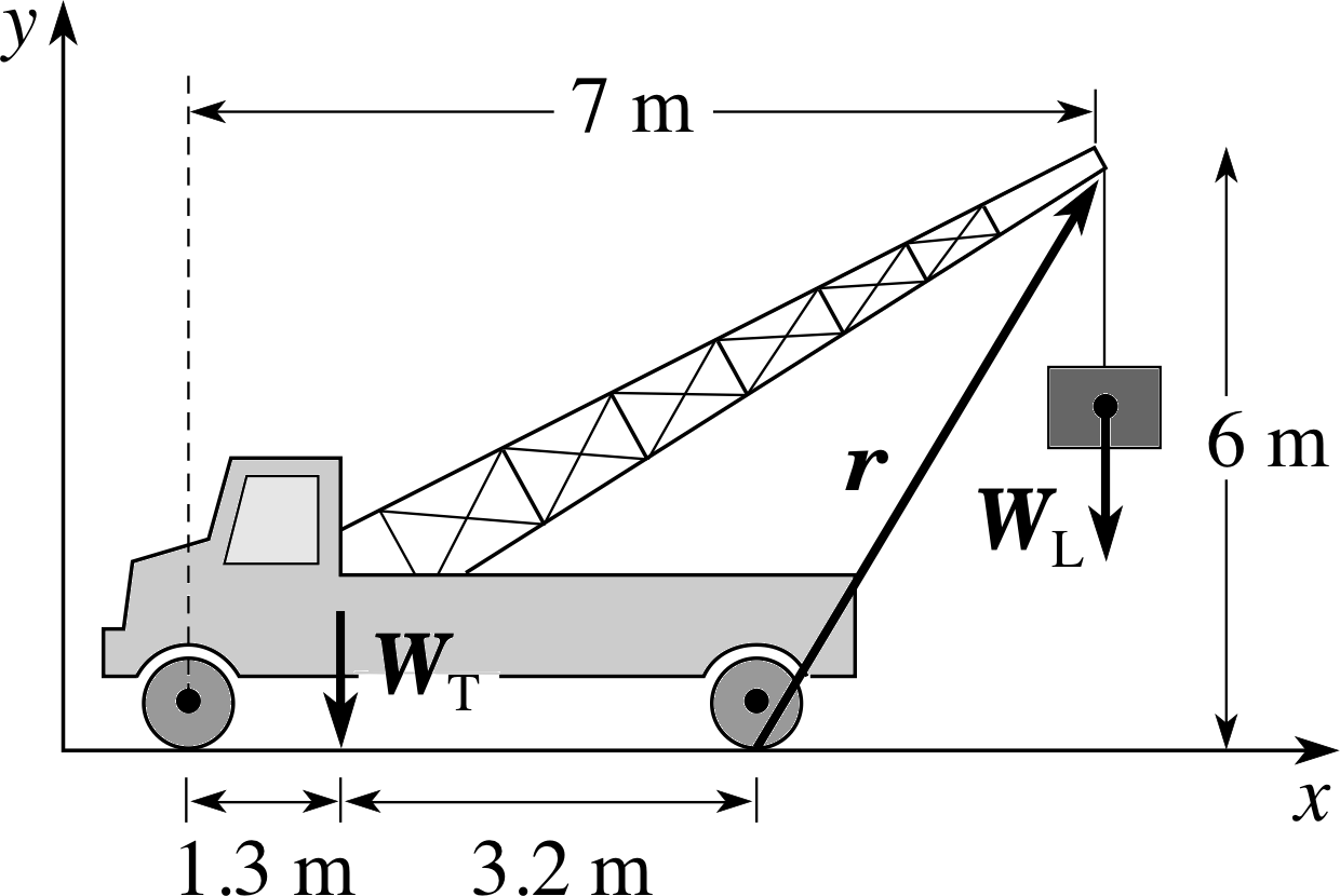
Figure 17 A crane–truck for Questions E2 and E3. The z–axis points towards you.
Question E2 (A2 and A4)
The 4000 kg crane–truck in Figure 17 has a centre of mass 1.3 m behind the front wheels. The distance between front and rear wheels is 4.5 m. If the top of the crane is 6 m above ground level and 7 m behind the front wheels calculate the maximum safe load which it can lift. Use scalar notation.
Answer E2
When the truck is just about to tilt under the load, the line of contact between the rear wheels and the ground becomes the fulcrum. The moment ΓL of the load WL, is
ΓL = −WL × (7 − 4.5) m = −WL × (2.5 m)
where the negative sign indicates that the associated rotation is clockwise.
The moment ΓT of the weight of the truck WT about the same fulcrum is
ΓT = (4000 kg) × (10 m s−2) × (3.2 m) = 1.3 × 10⁵ N m
where the positive sign indicates that the associated rotation is anticlockwise.
Thus ΓT + ΓL = 0 = 1.3 × 10⁵ N m − WL × (2.5 m) and WL = 1.3 × 10⁵ N m/2.5 m = 5.2 × 10⁴ N
The maximum safe load will therefore be 5.2 × 10³ kg.
(Reread Subsection 2.3 and 2.4 if you had difficulty with this question.)
Question E3 (A5, A6 and A7)
Consider again the crane–truck in Figure 17 and let the position vector r join the point of contact of the rear wheels to the top of the crane. Express r in terms of unit vectors of the given coordinate system and calculate the vector product of r and the maximum safe weight vector WL.
Answer E3
The components of r can be obtained from Figure 17. They are x = 2.5 m and y = 6 m. Choosing unit vectors i and j in the horizontal and vertical directions, respectively, the position vector of the load with respect to the chosen origin is r = (2.5 i + 6 j) m. The load weight vector is
WL = 5.2 × 10⁴(− j) N
where the negative sign indicates a downward force. The vector product (which gives the load torque) is
r × WL = (2.5 i + 6 j) m × 5.2 × 10⁴ (− j) N = −2.5 × 5.2 × 104 i × j = −1.3 × 10⁵ k
which is directed along the negative z–axis, or into the plane of Figure 17.
(Reread Subsections 3.1 and 3.2 if you had difficulty with this question.)
Question E4 (A5, A6, A7, A8, A10, A11 and A12)
If you allowed yourself to fall flat from a standing position, keeping rigid, on to a soft mattress, estimate (a) your angular speed and (b) the magnitude of your angular acceleration as you hit the mattress. Write down vector expressions in a specified coordinate system for (c) your angular velocity and (d) angular acceleration at impact.
For the purposes of this question, you may treat yourself as a thin uniform rigid rod. The moment of inertia of a thin rod of mass M and length L about an axis through its centre of mass and perpendicular to its length is :
$I_{\rm{cm}} = \frac{1}{12}ML^2$
Answer E4
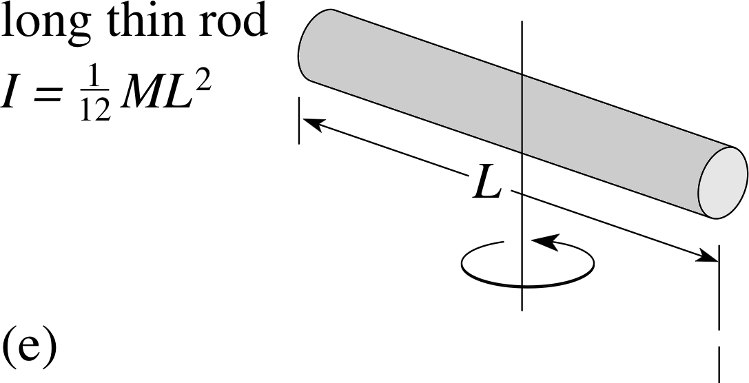
Figure 16e See Answer E4.
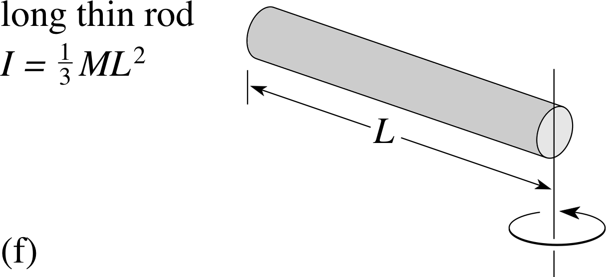
Figure 16f See Answer E4.
For the purposes of the estimate you may treat your body as a rod of mass M = 70 kg and of length L = 1.7 m. The moment of inertia of a rod of mass M and length L about an axis perpendicular to its length and through its centre of mass is Icm = M (L2/12) (see Figure 16e). The axis of rotation is a line on the ground running through your feet and perpendicular to your body. Let the moment of inertia about this axis be IG. Then the parallel–axis theorem gives IG = Icm + M (L/2)2
so$I_{\rm{G}} = \frac{1}{12}ML^2+\frac14ML^2 = \frac13ML^2$ = 67.4 kg m
(This may be seen directly in Figure 16f also.)
When you fall flat the loss in gravitational potential energy is equal to the gain in kinetic energy. The centre of mass of a rod is at its geometric centre so, equating the loss of gravitational energy to the gain in rotational kinetic about the axis on the ground gives MgL/2 = IGω2/2 so that ω = (MgL/IG)1/2.
(a) ω = (MgL/IG)1/2 = (3MgL/ML2)1/2 = (3g/L)1/2 which is independent of mass. Hence ω = (3 × 10 m s−2/1.7 m)1/2 = 4.2 rad s−1.
(b) Since Γ = Iα we need the value of Γ due to gravity at impact. This is Γimpact = MgL/2 = 70 kg × 10 m s−2 × 0.85 m = 6.0 × 10² N m.
Then α = Γ/IG = 6.0 × 10² N m/(67.4 kg m2) = 8.9 rad s−2.
(c) Suppose the coordinate system is such that you rotate clockwise in the (x-z) plane when viewed from the positive y–axis. Your angular velocity vector will then be ω = −4.21 j rad s−1.
(d) Your angular acceleration vector will then be α = −8.91 j rad s−2, since your angular velocity is increasing along the negative y–direction.
(Reread Section 5 if you had difficulty with this question.)
Question E5 (A12)
(a) Write down a general expression relating the kinetic energy of a cylinder rolling down a plane to its translational kinetic energy and its rotational kinetic energy about its central axis. (b) From this expression, deduce a general formula relating the angular speed to the effective vertical height fallen and the moment of inertia.
Answer E5
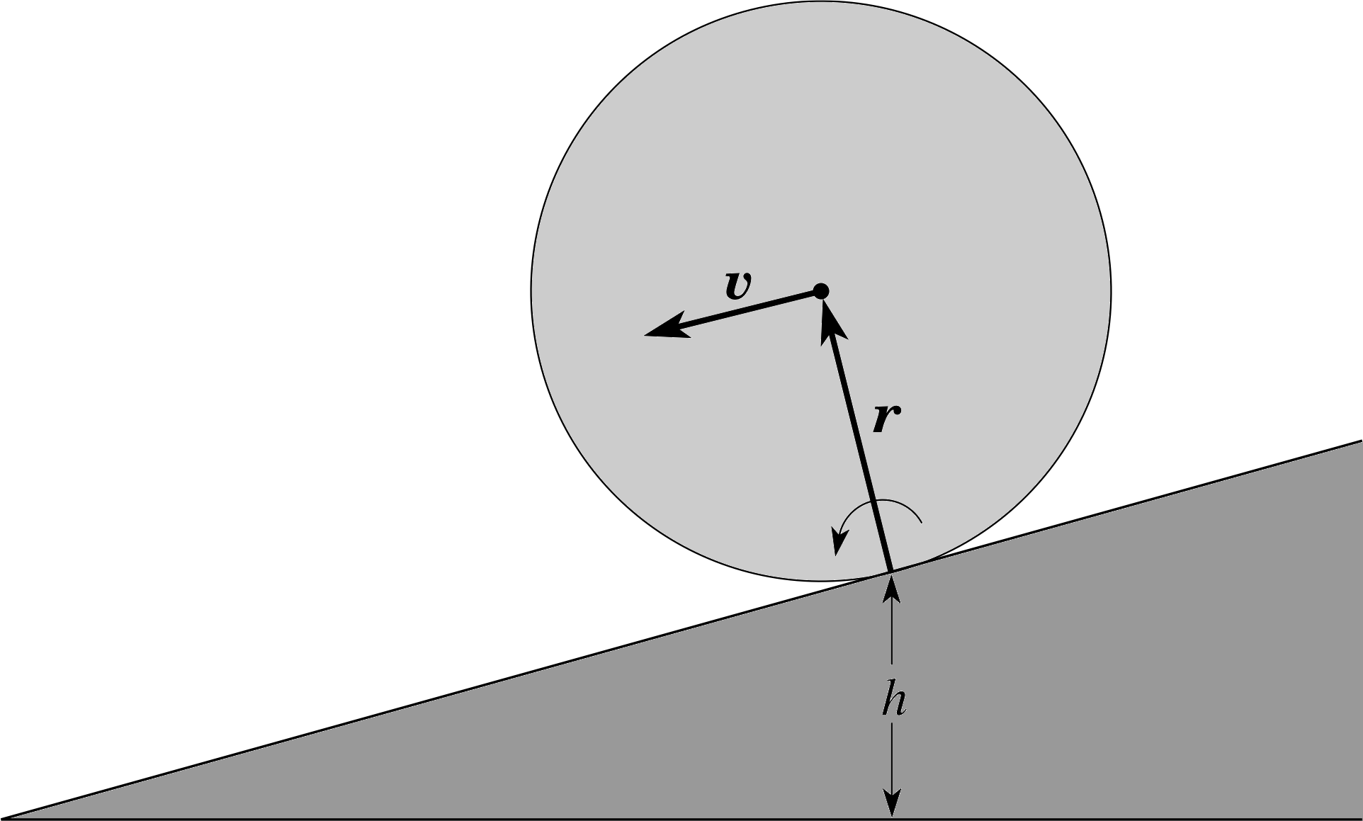
Figure 22 See Answer E5.
The translational kinetic energy is Mυ2/2 (see Figure 22) and the rotational kinetic energy about the central axis is Icmω2/2.
(a) The total kinetic energy Ekin = Mυ2/2 + Icmω2/2. Since υ = rω we can write this total kinetic energy as:
Ekin = M (rω)2/2 + Icmω2/2 = (Mr2 + Icm)ω2/2.
(b) The loss of gravitational energy in falling a height h = Mgh = gain in kinetic energy. So
Mgh = (Mr2 + Icm)ω2/2 and $\omega = \sqrt{\left(\dfrac{2Mgh}{Mr^2+I_{\rm cm}}\right)}$
(This expression can be further simplified if we know Icm, but this depends on whether the cylinder is solid or hollow.)
(Reread Section 5 if you had difficulty with this question.)
Question E6 (A9 and A12)
When a cylinder or sphere rolls down an inclined surface under gravity the gain in kinetic energy is equal to the loss in gravitational potential energy. Suppose three cylinders are made from different materials such that they have identical external dimensions and mass. They differ in that one cylinder is solid, one is hollow and thick-walled, while the other is hollow and thin-walled. All three cylinders are started together at the top of an inclined plane and roll down the slope, without slipping. Do they all arrive at the bottom simultaneously, or, if not, what is their arrival sequence? Explain your reasoning.
Answer E6
The question is answered by discovering the rank order of the angular speeds of the three cylinders at the bottom of the slope – since they are rolling without slipping and have identical sizes, this order is also the rank order of their speeds. Since the same amount of gravitational potential energy is available for each, their final total kinetic energies must be the same. Therefore:
Isolid (ωsolid)2 = Ithick (ωthick)2 = Ithin (ωthin)2
For a given same mass the moment of inertia increases with the distance from the axis and so it follows that:
Isolid < Ithick < Ithin and at the bottom ωsolid > ωthick > ωthin
The solid cylinder arrives at the bottom of the slope first, then comes the thick–walled cylinder and finally the thin–walled cylinder.
(Reread Section 5 if you had difficulty with this question.)
Question E7 (A3, A11 and A12)
(a) Calculate the rotational kinetic energy of the Earth, assuming it is a uniform solid sphere of mass 5.98 × 1024 kg and radius 6.38 × 10⁶ m. (b) Tidal friction and other factors cause the Earth’s rotation to slow down and the day is lengthening at the rate of 0.7 s every century. Calculate the power loss.
Answer E7
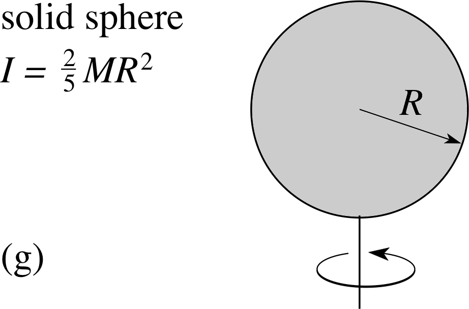
Figure 16g See Answer E7.
From Figure 16g the moment of inertia of a sphere about a central axis is related to its mass M and radius r by Icm = 2Mr2/5.
(a) So Icm = 2 × 5.98 × 1024 kg × (6.38 × 106 m)2/5 = 9.74 × 1037 kg m2
(b) ω = 2π/T = 2π/(24 × 60 × 60 s) = 7.27 × 10⁻⁵ rad s−1.
So the kinetic energy is
Ekin = Icmω2/2 = 9.74 × 1037 kg m2 × (7.27 × 10−5rad s−1)2/2 = 2.58 ×1029 J.
Loss of rotational kinetic energy in a century is Icm(ω12 − ω22)/2, where ω1, ω2 are the angular speeds of the Earth a century apart. Since ω1 and ω2 are almost equal we need to use more significant figures in the calculation:
ω1 = 7.2722052 × 10⁻⁵ rad s−1 and ω2 = 2π/(24 × 60 × 60 + 0.7) = 7.272463 × 10−51rad s−1
The loss of kinetic energy per century ∆Ekin is:
∆Ekin = Icm(ω1 − ω2)/2 = 4.17 × 1024 J.
The power loss = energy loss per second = 4.17 × 1024 J/(100 × 365.25 × 24 × 60 × 60 s) = 1.32 × 10¹⁵ W
(Reread Subsections 5.3 if you had difficulty with this question.)
Study comment This is the final Exit test question. When you have completed the Exit test go back and try the Subsection 1.2Fast track questions if you have not already done so.
If you have completed both the Fast track questions and the Exit test, then you have finished the module and may leave it here.
Study comment Having seen the Fast track questions you may feel that it would be wiser to follow the normal route through the module and to proceed directly to the following Ready to study? Subsection.
Alternatively, you may still be sufficiently comfortable with the material covered by the module to proceed directly to the Section 6Closing items.